Automatic detection of patient body profile and intelligent positioning of patient

a patient body profile and automatic detection technology, applied in the field of imaging system, can solve the problems of inaccurate positioning process, slow whole scanning process, inaccuracy in detection, etc., and achieve the effect of quick and accurate movemen

Active Publication Date: 2014-07-31
GE MEDICAL SYST GLOBAL TECH CO LLC
View PDF7 Cites 18 Cited by
  • Summary
  • Abstract
  • Description
  • Claims
  • Application Information

AI Technical Summary

Benefits of technology

[0006]One object of the present invention is to solve at least one of the above identified problems and provide techniques of detecting a patient profile and automatically setting the height of a scan support table according to the patient profile, thereby positioning the patient more quickly and more accurately and improving the image quality.
[0007]Another object of the present invention is to provide a technique of quickly and accurately moving an interested location of a patient to a gantry in a direction in which the patient goes in and out a bore.
[0012]With the imaging system and the method of positioning a scan object in an imaging system as mentioned above, the present invention can quickly and accurately move the interested location of the scan object to the scanning plane of the imaging system and align the center of the interested location of the scan object with the center of the scanning plane.

Problems solved by technology

This makes the whole scanning process slow.
Additionally, since there is no effective means for positioning the patient, patient positioning depends on the doctor's observation to determine whether the patient is positioned in an appropriate position, which depends on the doctor's experience and makes the positioning process inaccurate.
Thus, inaccuracy in detection arises and the imaging quality is affected.

Method used


Image

  • Automatic detection of patient body profile and intelligent positioning of patient
  • Automatic detection of patient body profile and intelligent positioning of patient
  • Automatic detection of patient body profile and intelligent positioning of patient

Examples


Embodiment Construction

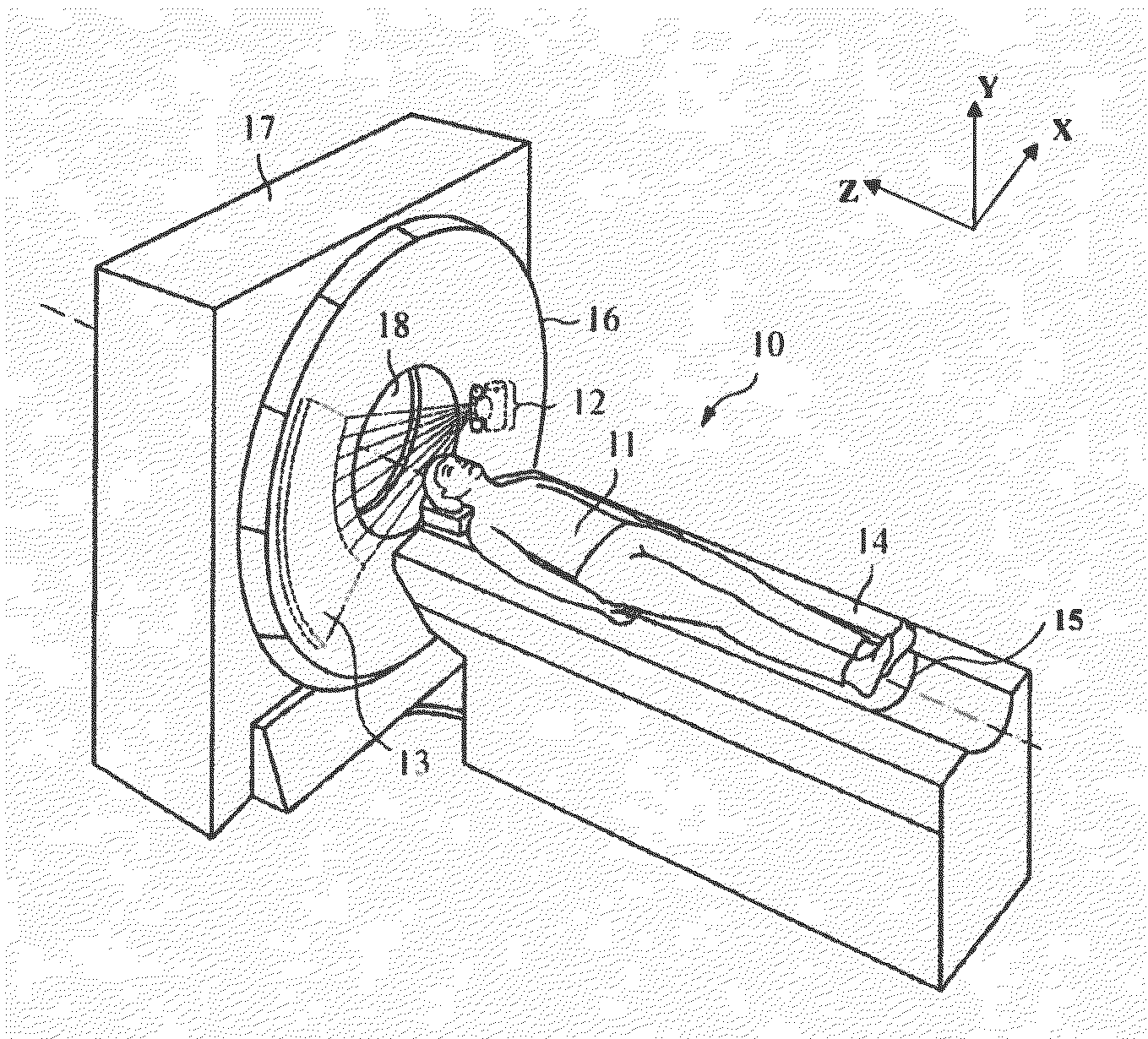
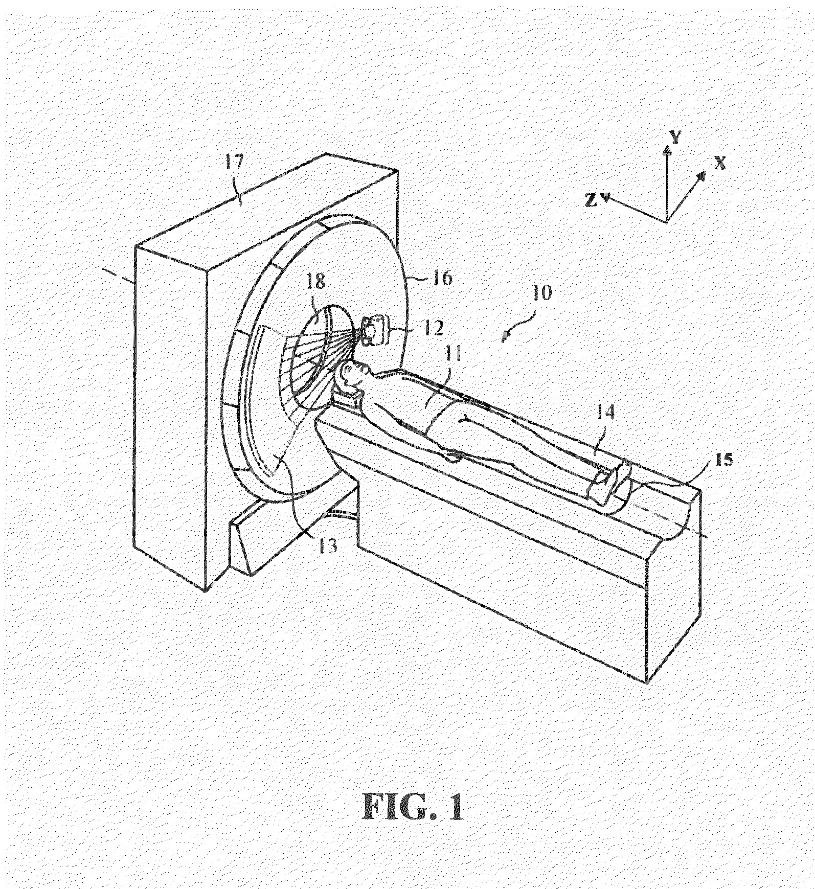
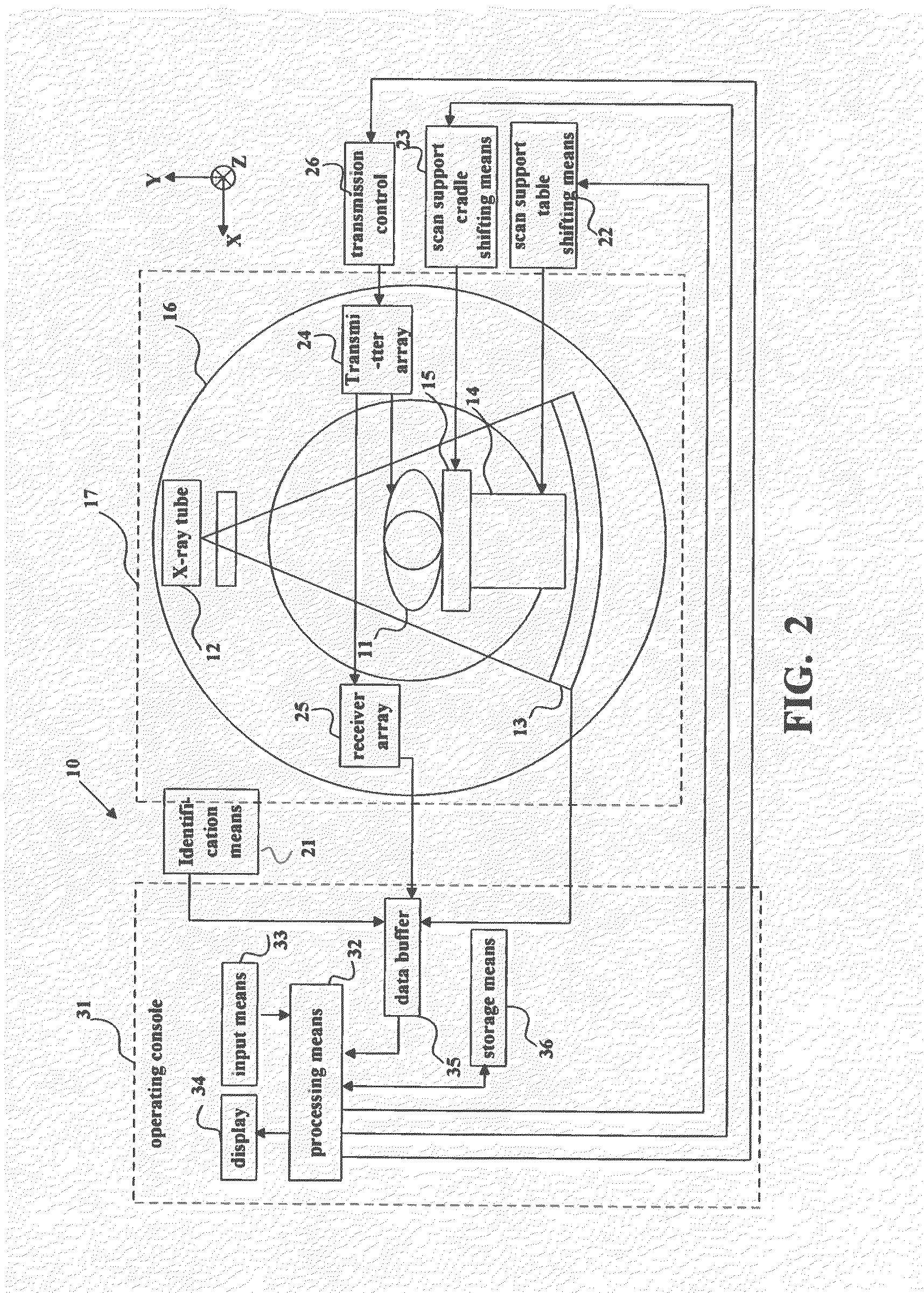
[0024]In the following detailed description, embodiments of the present invention are described with reference to the accompanying drawings. The CT (Computed Tomography) system described hereinafter is by way of example, and it shall be appreciated by persons skilled in the art that the principle of the present invention is also applicable to other imaging systems such as MRI (Magnetic Resonance Imaging) systems and PET (Positron Emission Tomography) systems. Furthermore, the patient described hereinafter as the scan object is by way of example, and it shall be appreciated by those skilled in the art that the principles of the present invention are also applicable to scan objects such as animals and plants, goods and the like.

[0025]The term “electrically connected” described in the present disclosure refers to a direct or indirect electrical connection between two devices. For example, description that a first device is electrically connected to a second device can mean that the fir...


PUM


Abstract

An imaging system configured to automatically detect a patient's body profile and to position the patient. The imaging system includes a scan support member configured to support a scan object, a processing device; and an identification device electrically connected to the processing device. The scan support member includes a machine identifiable code representing a distance from a position of the machine identifiable code to one end of the scan support member. The identification device is configured to identify the machine identifiable code, to decode the distance represented by the machine identifiable code and to send the distance represented by the machine identifiable code to the processing device. The processing device determines a distance from an interested location of the scan object to a scanning plane of the imaging system according to the distance represented by the machine identifiable code.

Description

TECHNICAL FIELD[0001]The present invention relates to an imaging system, and more particularly, to automatic detection of a patient body profile and intelligent positioning of a patient within an imaging system.BACKGROUND ART[0002]In such imaging systems as CT (Computed Tomography), prior to scanning, a center of an interested location of a patient, the location of interest needs to be aligned with a center of a CT gantry.[0003]In the existing CT imaging system, the general positioning process is as follows: first let the patient lie on the scan bed, next, the doctor utilizes the pedal or the like to move the scan bed to a fixed height and position; then, the laser positioning lamp, which is adjacent to the X-ray tube is turned on, and a location of the patient's body irradiated by the laser positioning lamp is observed while finely tuning the position of the scan bed, such that the laser positioning lamp irradiates the scan reference location of the patient; next, the height of the...

Claims


Application Information

Patent Timeline
Patent Type & Authority Applications(United States)
IPC IPC(8): A61B6/04G01R33/30A61B6/03
CPCA61B6/04G01R33/30A61B6/037A61B6/032G01R33/28A61B6/08A61B6/545A61B6/589A61B2562/08A61B6/03A61B6/0487A61B5/055A61B5/704
Inventor XU, HUIJUN
Owner GE MEDICAL SYST GLOBAL TECH CO LLC
Why Eureka
Try Eureka