
Antenna device for portable terminal

Active Publication Date: 2014-07-31
SAMSUNG ELECTRONICS CO LTD
View PDF7 Cites 58 Cited by
  • Summary
  • Abstract
  • Description
  • Claims
  • Application Information

AI Technical Summary

Benefits of technology

The present invention provides an antenna device that can be installed in a miniaturized and lightened portable terminal and still provide stable radiation performance. It improves design flexibility by using conductive components in the portable terminal as a radiator, and also improves efficiency by using the internal space of the portable terminal more effectively.

Problems solved by technology

However, when considering the portability, miniaturization and lightening of portable terminals are needed.
However, the thickness of portable terminals may be reduced in order to miniaturize and lighten the portable terminals as the size of displays is increased, and the ability to provide antenna devices capable of securing a stable radiation performance while being installed inside of portable terminals may be limited.
In addition, as a plurality of antenna devices are installed in a single terminal in order to use various types of communication systems and standards, for example, a variety of mobile communication standards, wireless Local Area Network (LAN) standards, Bluetooth, Near Field Communication (NFC), and any other communication systems and standards, difficulties in arranging the antenna devices inside of a portable terminal may increase.

Method used


Image

  • Antenna device for portable terminal
  • Antenna device for portable terminal
  • Antenna device for portable terminal

Examples


Embodiment Construction

[0024]The following description with reference to the accompanying drawings is provided to assist in a comprehensive understanding of exemplary embodiments of the invention as defined by the claims and their equivalents. It includes various specific details to assist in that understanding but these are to be regarded as merely exemplary. Accordingly, those of ordinary skill in the art will recognize that various changes and modifications of the embodiments described herein can be made without departing from the scope and spirit of the invention. In addition, descriptions of well-known functions and constructions may be omitted for clarity and conciseness.

[0025]The terms and words used in the following description and claims are not limited to the bibliographical meanings, but, are merely used by the inventor to enable a clear and consistent understanding of the invention. Accordingly, it should be apparent to those skilled in the art that the following description of exemplary embod...


PUM


Abstract

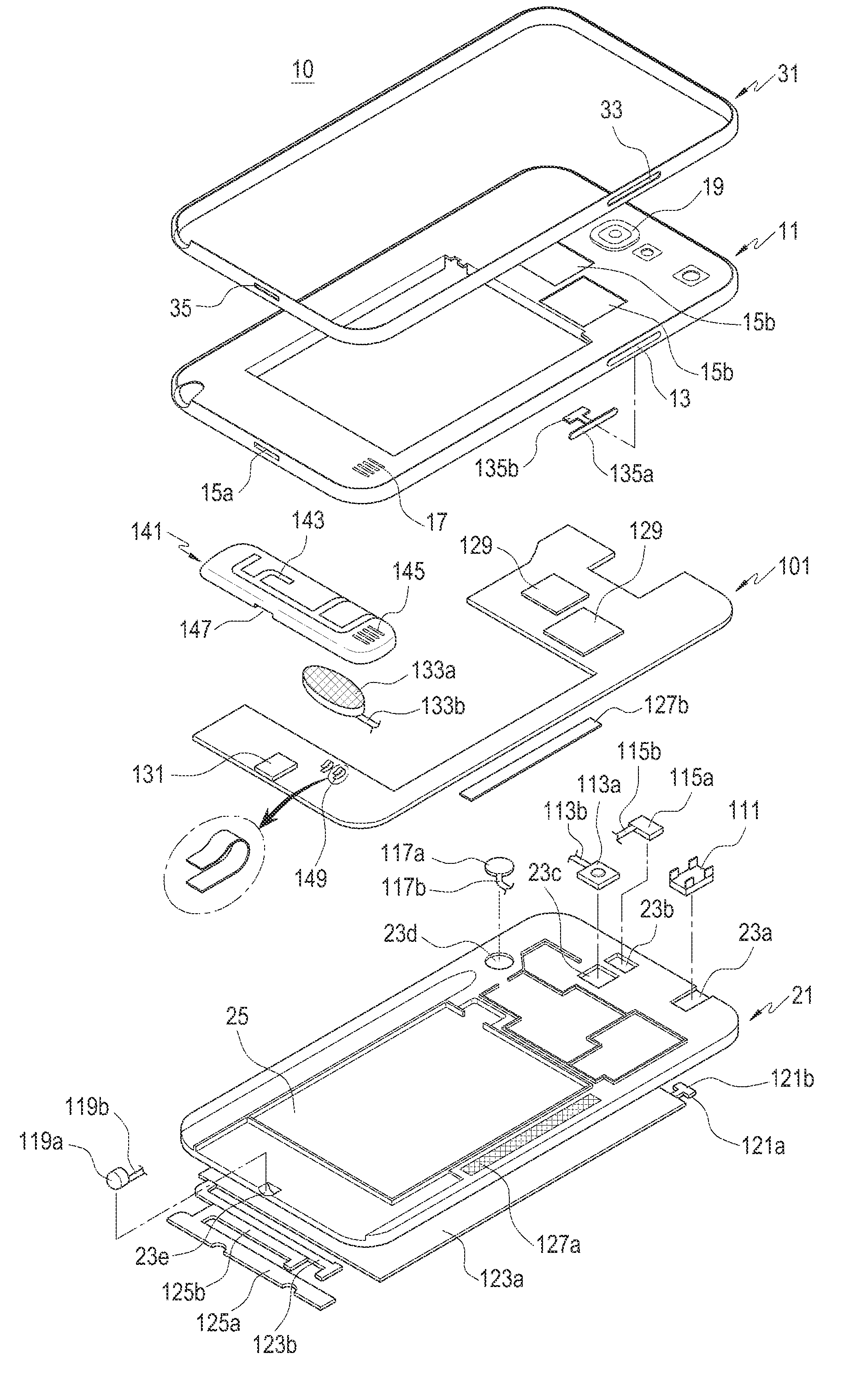
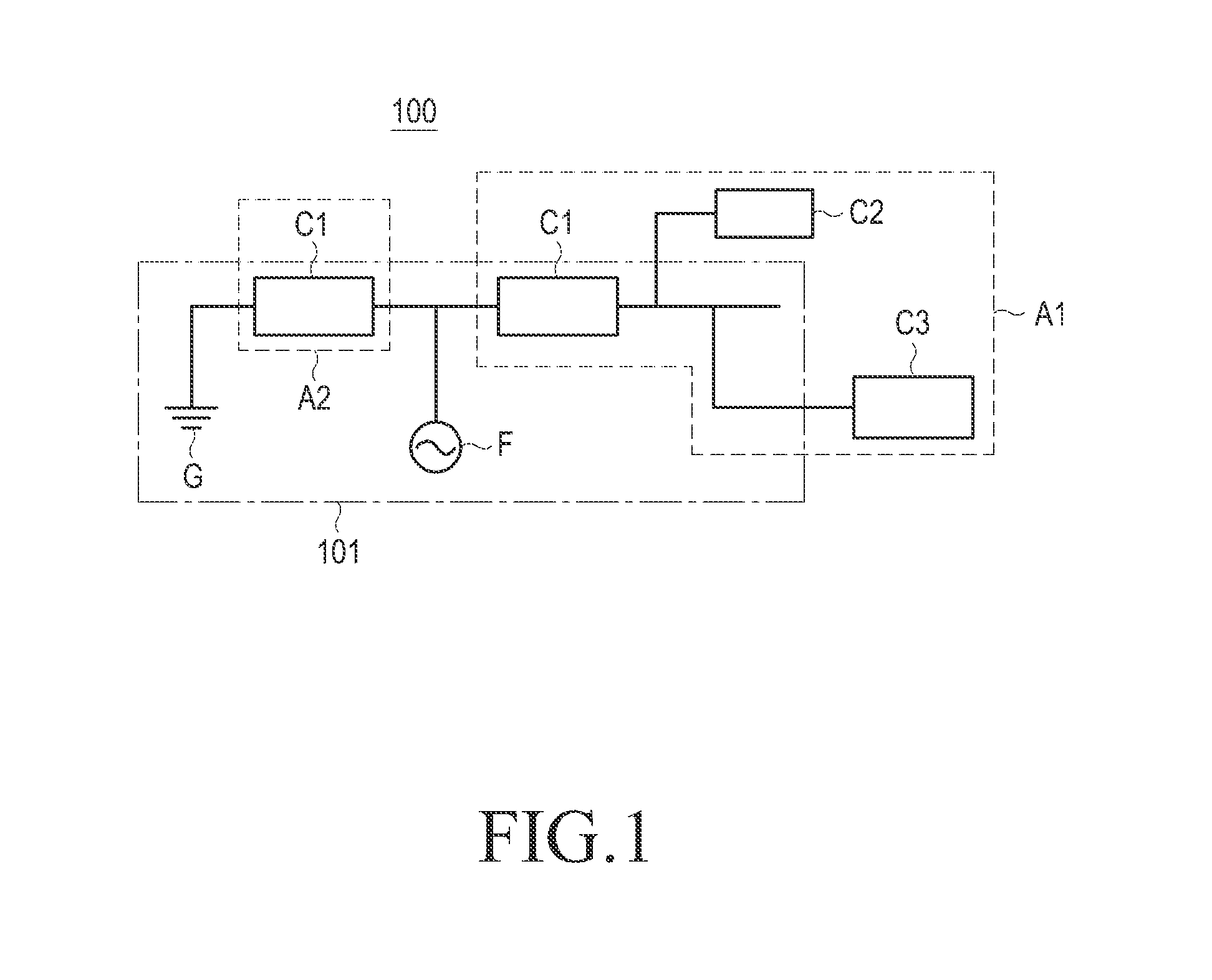
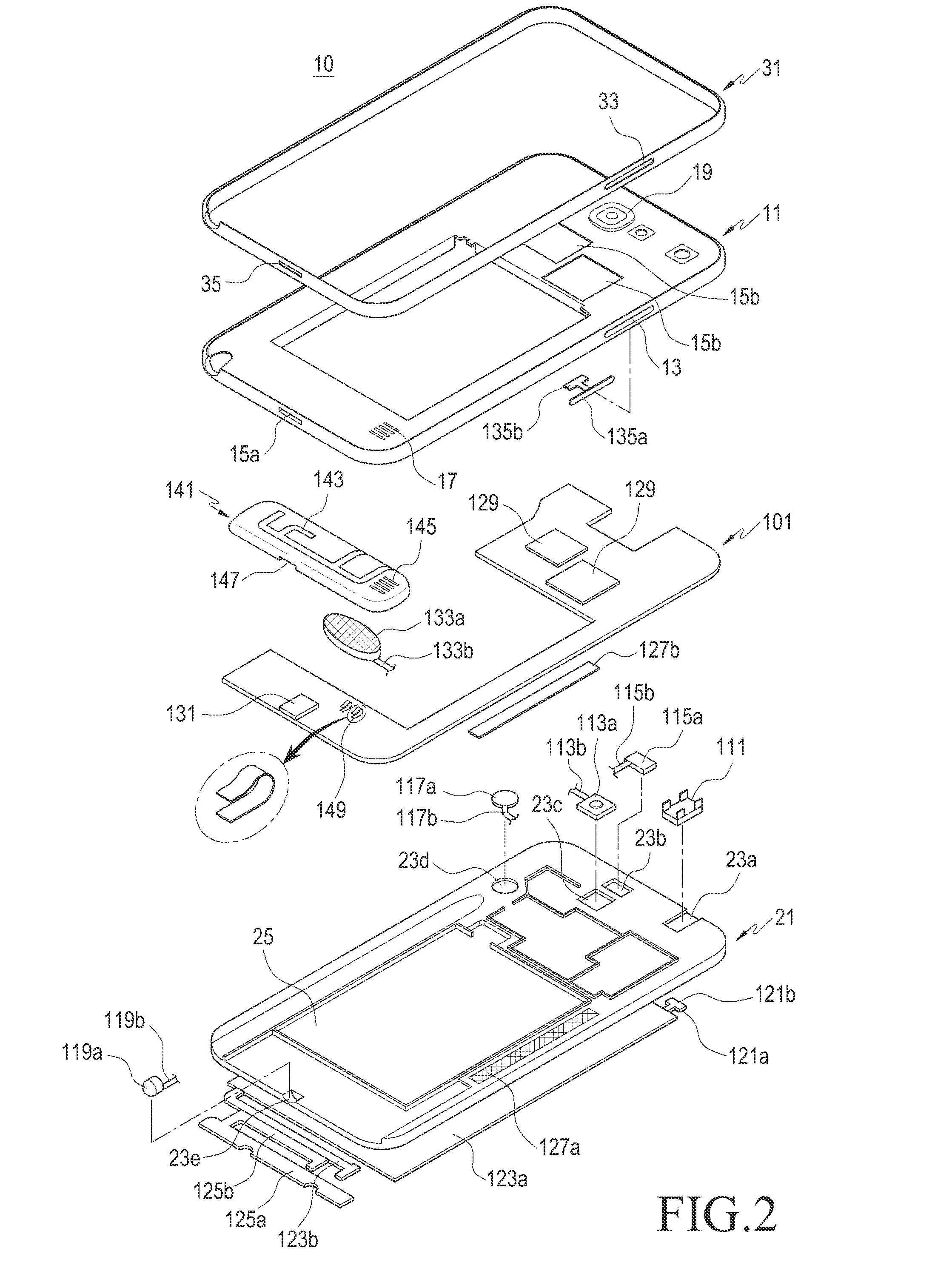
An antenna device of a portable terminal including conductive components is provided. The antenna device includes a first radiator connected to a power feeding unit of the portable terminal and a second radiator connected to each of the power feeding unit and a ground part of the portable terminal. At least one of the conductive components is connected to at least one the first radiator and the second radiator. The conductive components may be used as a radiator of the antenna device such that the antenna device may be easily installed within an inner space of a miniaturized and lightened portable terminal and the inner space of the portable terminal may be efficiently used.

Description

PRIORITY[0001]This application claims the benefit under 35 U.S.C. §119(a) of a Korean patent application filed on Jan. 30, 2013 in the Korean Intellectual Property Office and assigned Serial No. 10-2013-0010477, the entire content of which is hereby incorporated by reference.BACKGROUND OF THE INVENTION[0002]1. Field of the Invention[0003]The present invention relates to a portable terminal. More particularly, the present invention relates to an antenna device that enables wireless communication of a portable terminal.[0004]2. Description of the Related Art[0005]A portable terminal may be a device that allows a user to use a communication function, such as voice communication or short message transmission, a multimedia function, such as playing music or reproducing a moving image, an entertainment function, such as a game while the user is carrying the portable device, or any other similar and / or suitable function that may be executed on a portable terminal or portable electronic dev...

Claims


Application Information

Patent Timeline
IPC IPC(8): H01Q1/24H01Q5/10
CPCH01Q1/44H01Q1/243H01Q13/10H01Q1/24H01Q5/10H01Q5/00H01Q1/48H01Q1/50
Inventor HWANG, SOON-HOPARK, SUNG-KOOLEE, KYUNG-JAEBYUN, JOON-HO
Owner SAMSUNG ELECTRONICS CO LTD
Learn More