
Video Capture Attachment and Monitor for Optical Viewing Instrument

a technology of optical viewing and video capture, which is applied in the field of optical imaging devices, can solve the problems of physical holding of the viewing instrument in the way required for viewing, adding a layer of difficulty to the use of an optical viewing tool, and affecting the use of the viewing tool

Inactive Publication Date: 2014-07-31
JOHNS JR WILLIAM HENRY
View PDF18 Cites 6 Cited by
  • Summary
  • Abstract
  • Description
  • Claims
  • Application Information

AI Technical Summary

Benefits of technology

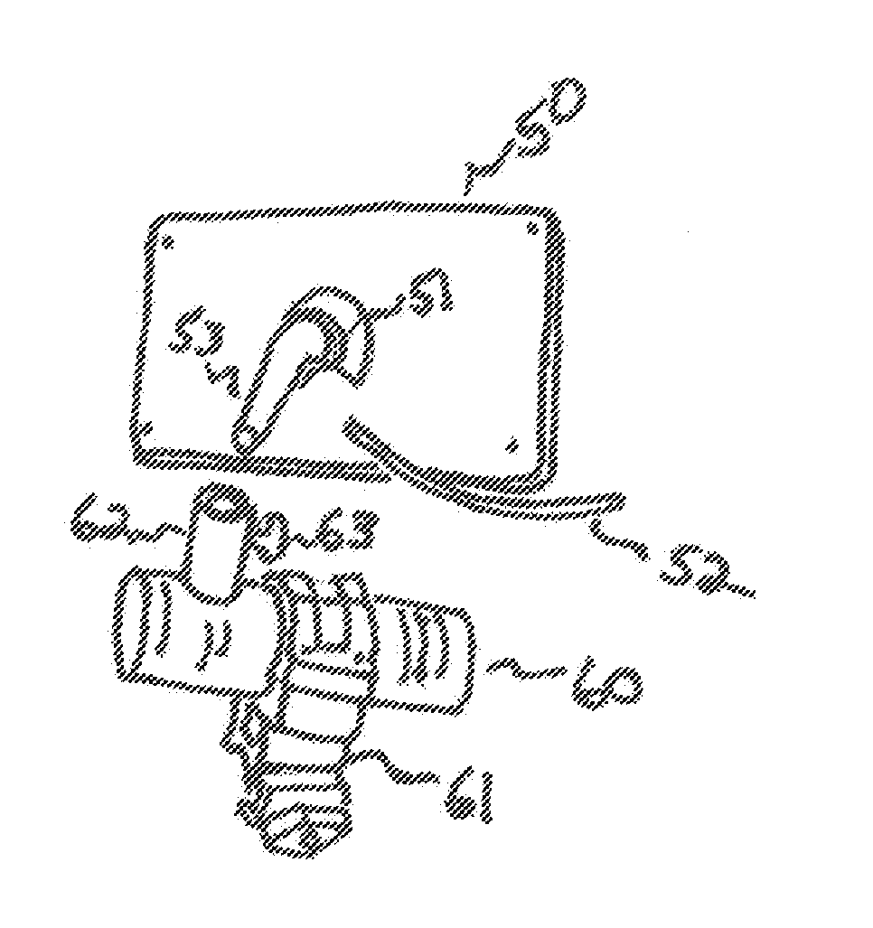
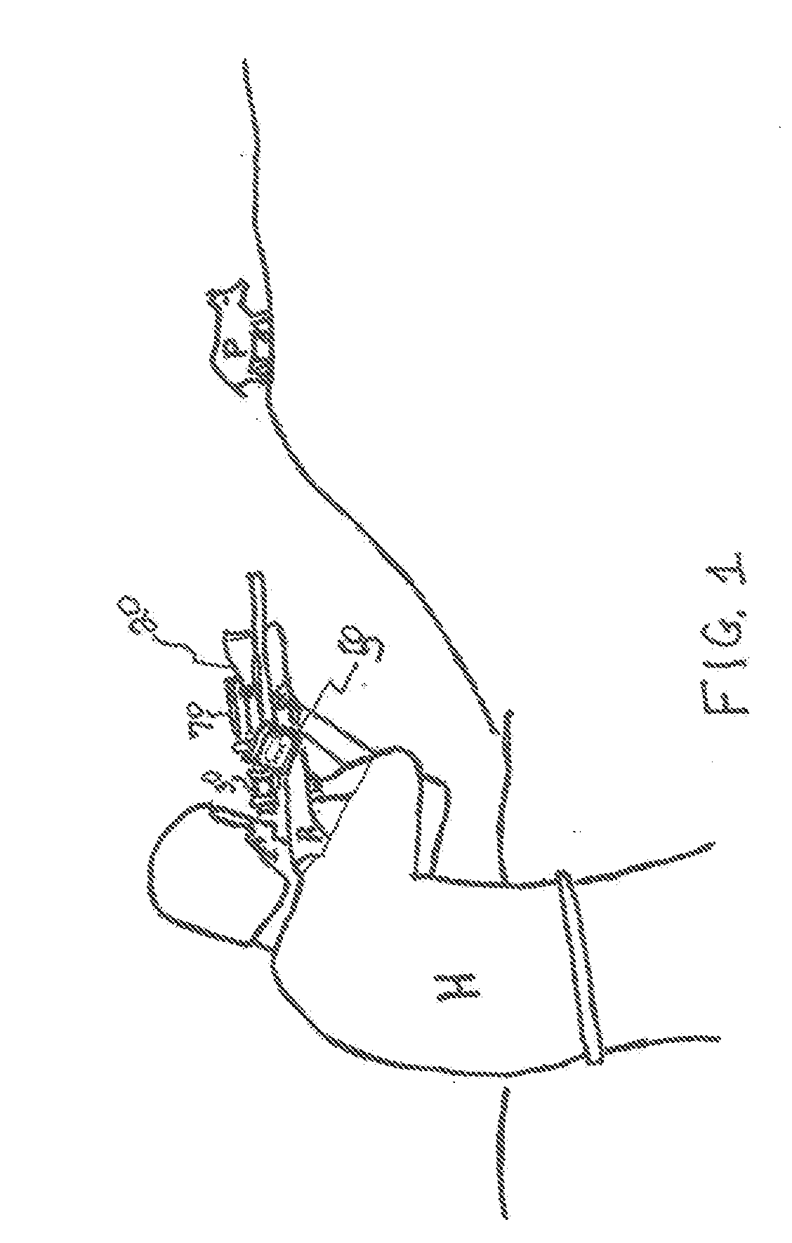
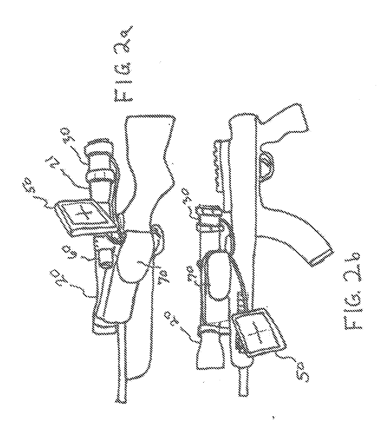
The present invention is a camera that can be attached to an optical viewing scope to capture live images and convert them into digital data. The camera can be attached at different points on the scope to focus on the image. The camera also has a display that can be attached to the scope, rifle, or other structures. The camera can be transmitted, stored, or displayed to any device with video input capabilities. These technical effects enable the capture and utilization of live images in a more convenient and efficient way.

Problems solved by technology

This type of viewing adds a layer of difficulty to using an optical viewing tool.
Focusing the eye through an eye piece may also be difficult for persons with certain visual impairments.
Physically holding the viewing instrument in a way required for viewing can be difficult for some persons.

Method used


Image

  • Video Capture Attachment and Monitor for Optical Viewing Instrument
  • Video Capture Attachment and Monitor for Optical Viewing Instrument
  • Video Capture Attachment and Monitor for Optical Viewing Instrument

Examples


Embodiment Construction

[0038]The present invention comprises various embodiments of an optical image capture and display device which is easily attachable and removable from an optical scope like a rifle scope. This device is attached in a way that enables the video image capture instrument to capture the real time images coming through the lens and or other mechanisms of the viewing instrument and transmit those images digitally to an electronic device. The instrument has video output connections that can be connected to monitors, transmitters, recorders, or any instrument with video input capabilities. The present invention includes a monitor that is attachable to and removable from the body of an optical scope or other viewing instrument. The monitor has electrical connections that can be connected to and disconnected from the optical video image capture instrument and a power supply. The primary purpose of this instrument is to enable the viewing of images without having to look into an eye piece. For...


PUM


Abstract

The present invention is an attachable and detachable video image capture and display instrument that comprises a digital video capture device that can easily be physically connected to a gun scope, spotting scope, telescope, microscope, monocular, binocular or other optical viewing instrument or optical instrument used for viewing or examining an object or scene. It has electronic output to a display device, recording instrument, computing instrumen video projection devise, or data transmission instrument by way of connections of various options including wires, blue tooth, cellular, or other methods of video and audio data transmission. The video data coming into the optical instrument can be viewed while it happens on various display monitors that are physically mounted to the optical instrument, or not physically mounted to the optical instrument. The image capture mode can he black and white, color, 3 dimensional, night vision, thermal vision, and all other imaging modes available in the industry. This device is capable of video output of image data that can be integrated with computer applications that use image technologies with examples including image recognition and motion detection algorithms.

Description

CROSS-REFERENCE TO RELATED APPLICATION[0001]This application claims the benefit of U.S. Provisional Patent Application Ser. No. 61 / 756514, filed Jan. 25, 2013.BACKGROUND OF THE INVENTION[0002]1. Field of the Invention[0003]The present invention comprises various embodiments of an optical imaging device related generally to a camera attachment for optical viewing instruments which is attachable and removable, or mechanically positioned with the ocular lens of an optical viewing instrument to capture real-time images that are projected through the lenses and convert the images into digital data that can he output to a viewing monitor, recording instrument, computing instrument, or transmitting device. The present optical instrument attachment enables a person or persons to view the images coming through the optical viewing instrument on a monitor that replaces the need for a person to physically look through an eye piece, and the image data can be stored or used in computing applicati...

Claims


Application Information

Patent Timeline
Patent Type & Authority Applications(United States)
IPC IPC(8): H04N5/30
CPCH04N5/2251F41G1/00F41J5/10F41G1/38
Inventor JOHNS, JR., WILLIAM HENRY
Owner JOHNS JR WILLIAM HENRY
Learn More