Vapor chamber structure

Inactive Publication Date: 2014-08-07
ASIA VITAL COMPONENTS SHENZHEN CO LTD
View PDF7 Cites 5 Cited by
  • Summary
  • Abstract
  • Description
  • Claims
  • Application Information

AI Technical Summary

Benefits of technology

The present invention aims to improve the heat dissipation of a vapor chamber structure. It achieves this by providing an effective means for heat transfer and remote heat dissipation, which significantly improves the overall heat dissipation of the vapor chamber.

Problems solved by technology

However, the size shrinking of the electronic apparatus is accompanied with the heat dissipation issue which becomes the major barrier against an improvement to the performance of the electronic apparatus and system.
The challenge caused by an increase in heat flux to cool the heated product is more severe than the total amount of the increased heat.
Due to the increase in heat flux, the overheating issue about the electronic products will occur for various sizes at any time, causing damage to and failure in the electronic components.
It has the advantages of a larger area for heat transfer and a fast heat transfer rate; however, its disadvantage is that it can not transfer and dissipate the heat to a remote end.
This is the main disadvantage of the VC.

Method used


Image

  • Vapor chamber structure
  • Vapor chamber structure
  • Vapor chamber structure

Examples


Embodiment Construction

[0016]The above objective and structural and functional features of the present invention will be described with reference to the preferred embodiments in the accompanying drawings.

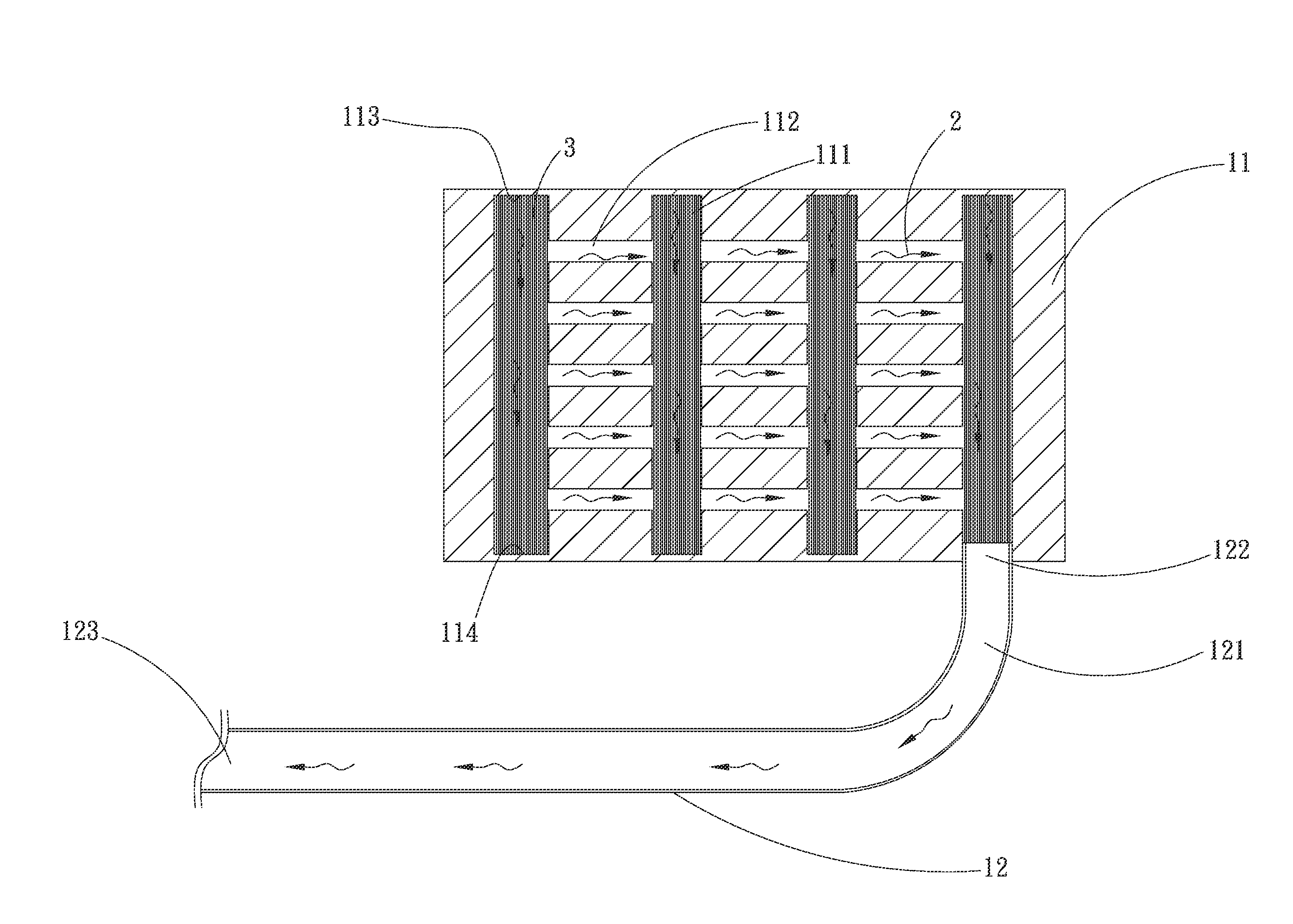
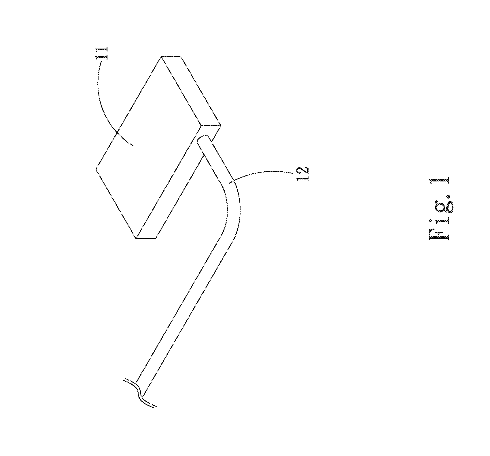
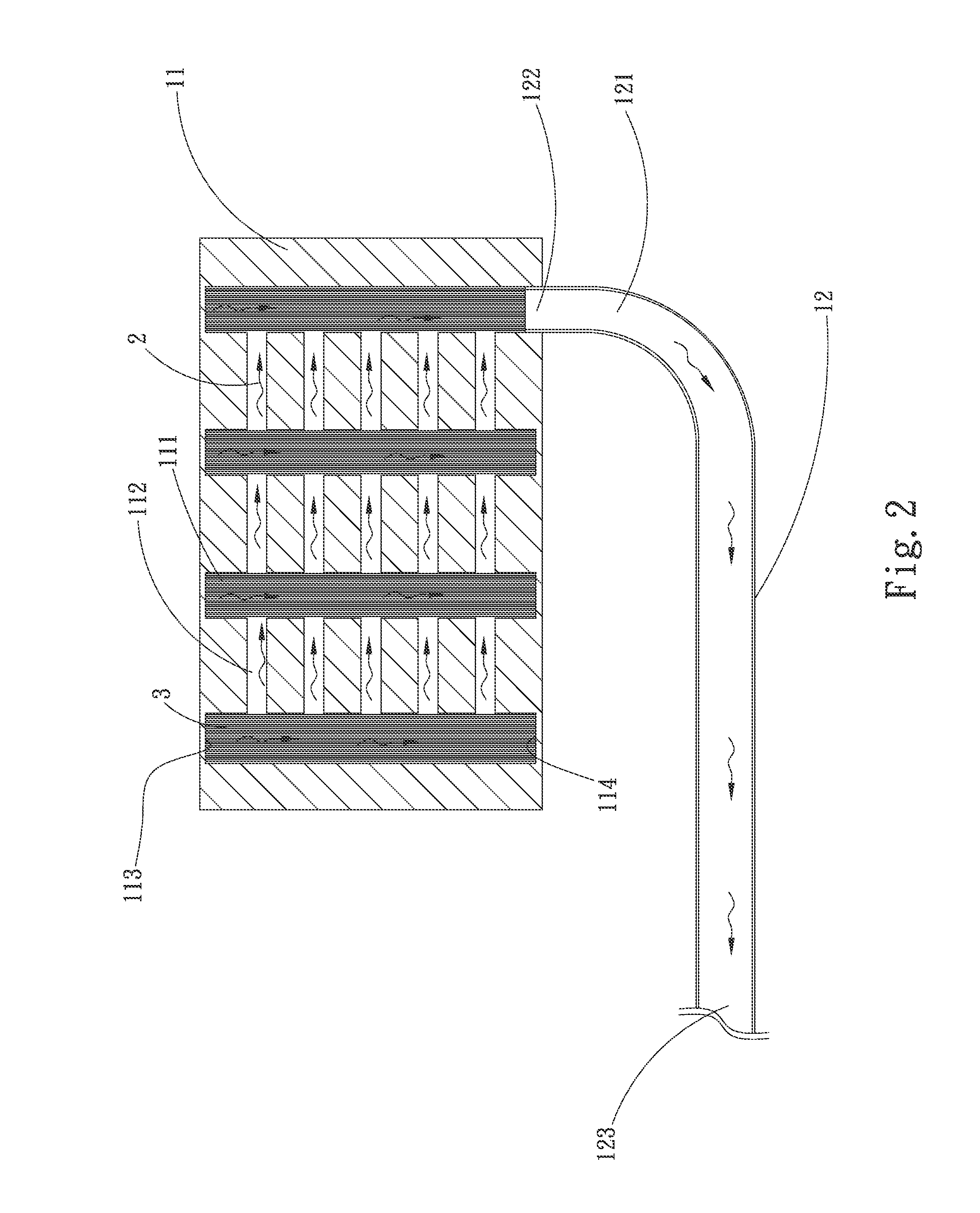
[0017]Please refer to FIGS. 1 and 2, which are the perspective view and cross-sectional assembled view of the improvement to a vapor chamber structure according to the first embodiment. As shown in FIGS. 1 and 2, the improvement to a vapor chamber structure according to the current embodiment comprises a first body 11, a second body 12, and a working fluid 2.

[0018]The first body 11 has a plurality of first channels 111 and a plurality of second channels 112, the first and second channels 111, 112 communicating with one another.

[0019]The first and second channels 111, 112 communicate with and intersect with one another at right angles. The first body 11 comprises a first enclosure side 113 and a second enclosure side 114 which seal two ends of the first channels 111, respectively.

[0020]The second body 12 h...


PUM


Abstract

An improvement to a vapor chamber structure comprises a first body, a second body, and a working fluid. The first body has a plurality of first channels and a plurality of second channels, the first and second channels communicating with one another. The second body has a third channel, the first and second bodies and the first, second, and third channels communicate with one another and has a wick structure and are filled with a working fluid. By means of such a design of the present invention, the first body has the effect of uniform heat dissipation and the remote heat dissipation can be achieved through the second body. Consequently, the whole heat dissipation can be considerably improved.

Description

BACKGROUND OF THE INVENTION[0001]1. Field of the Invention[0002]The present invention relates to an improvement to a vapor chamber structure and in particular to an improvement to a vapor chamber structure with a large area for uniform heat transfer and remote heat dissipation.[0003]2. Description of Prior Art[0004]With the compact size of the present electronic apparatus gradually becoming the appealing demand, each component of the electronic apparatus thus continues to shrink. However, the size shrinking of the electronic apparatus is accompanied with the heat dissipation issue which becomes the major barrier against an improvement to the performance of the electronic apparatus and system. Even the semiconductor sizes of the electronic components continue to shrink; there is still a constant demand for outstanding performance[0005]When the semiconductor size shrinks, the induced heat flux increases consequently. The challenge caused by an increase in heat flux to cool the heated ...

Claims


Application Information

Patent Timeline
IPC IPC(8): F28D15/04
CPCF28D15/04F28D15/0266F28D15/0275
Inventor YANG, HSIU-WEI
Owner ASIA VITAL COMPONENTS SHENZHEN CO LTD
Why Eureka
Try Eureka