Elevator

a technology of elevators and lifts, applied in the field of elevators, can solve the problems of dangerous situations, unplanned moving of elevators out of the operating position, and difficulty in preventing unplanned moving of elevators

Active Publication Date: 2014-08-07
KONE CORP
View PDF4 Cites 6 Cited by
  • Summary
  • Abstract
  • Description
  • Claims
  • Application Information

AI Technical Summary

Benefits of technology

[0004]The aim of the invention is to solve the problems of prior-art solutions and to produce an elevator that is improved with respect to the safety devices of the elevator car. More particularly it is endeavored with the invention to prevent unintentional displacement of the protective wall of the elevator car out of its intended position. Further, it is endeavored with the invention to disclose a simple and space-efficient solution for locking a protective wall into its operating position.
[0007]In a preferred embodiment a force (F2) is arranged to be exerted on the locking means in the retracted position, pushing it towards the locking position, which force is preferably the gravity of the earth and / or the spring force of a possible spring means. In this way automatic displacement into locking can be achieved without any manual procedures and without complex actuators.
[0012]The locking means is preferably an elongated, flexurally stiff member, which when in the retracted position is in a vertical position. Thus it can displaced simply to extend to below and to support the protective wall adequately from below. Also a vertical linear movement is thus easy to arrange.
[0013]In a preferred embodiment the locking means is an elongated, flexurally stiff member, and the locking means is arranged to move between a locking position and a retracted position with a linear movement, preferably with a longitudinal linear movement of the locking means. Thus its path of movement does not require a large space, and space can be found for it into which it can be fitted when it is in the retracted position. It is very simple, in terms of the construction, to arrange a linear movement and to form the movement to be controlled. As the linear movement occurs in the longitudinal direction, the usage of transverse space in relation to the stiffening effect to be achieved is small.
[0017]In a preferred embodiment the holding means are arranged to release the protective wall if the elevator car stops between consecutive floor landings. In this way the displacement of the protective wall into the operating position can be achieved automatically and the elevator switches automatically into a safe mode in the case of the aforementioned exceptional situation. For this purpose the elevator preferably comprises means, which are able to disconnect the hold of the holding means if the elevator car stops between floor landings. These means can e.g. comprise a control, which disconnects the hold in the aforementioned situation, or disconnection of the safety circuit of the elevator can result in disconnection of the electrical energy needed for the hold of the holding means and thereby in release of the hold. The holding means are preferably electrically driven, e.g. with an actuator, such as acting with a solenoid actuator. The aforementioned ways to implement are simple and utilize existing elevator components.
[0020]In a preferred embodiment the aforementioned force (F1 and / or F2) is achieved without an electrically-driven actuator, e.g. gravity and / or with the spring force of a possible spring means. In this way the movement into the operating position / locking position is also safe from the viewpoint of equipment failure.

Problems solved by technology

A problem with a folding-type protective wall is that the unintended moving of it out of the operating position must somehow be prevented.
More particularly the folding of a protective wall out of the operating position under the weight of a person leaning on the protective wall could cause a dangerous situation.
The locking means have, however, been complicated and forming them to be durable and reliable in a space-efficient manner has been awkward.

Method used


Image

  • Elevator
  • Elevator
  • Elevator

Examples


Embodiment Construction

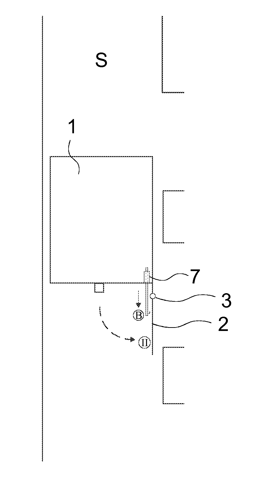
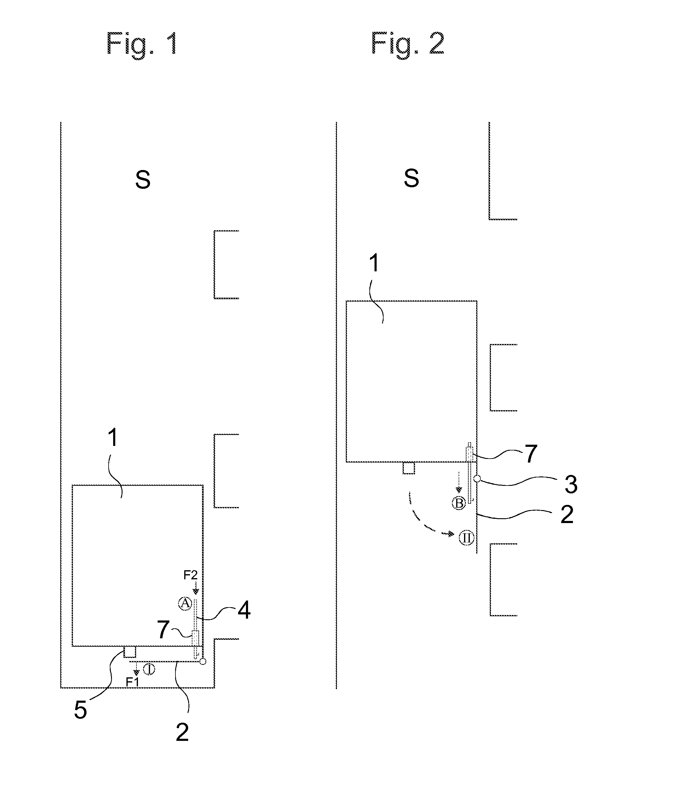
[0032]FIG. 1 presents an elevator according to the invention, which comprises an elevator car 1 configured to move in an elevator hoistway S, and floor landings, and a protective arrangement, which protective arrangement comprises a protective wall 2 connected to the bottom part of the elevator car 1. The protective wall 2, as presented in the figure, is in the retracted position I taking up little vertical space below the elevator car 1. In this way the elevator car 1 could be driven very close to the base of the pit of the elevator hoistway S. FIG. 1 presents the elevator car in a situation according to normal drive, wherein the elevator car 1 has stopped at the point of the (bottommost) floor landing, in which case the sill of the door aperture of the elevator car 1 is level with the sill of the floor landing. Since the elevator car 1 is in normal drive, there is no access from the floor landing to below the elevator car 1, and the protective wall does not need to be in the opera...


PUM


Abstract

An elevator having an elevator car configured to move in a hoistway, and floor landings, and a protective arrangement, which arrangement has a wall connected to the bottom of the car, which protective wall can be displaced between a vertical operating position and a retracted position folded out of the vertical operating position, and when in which operating position the wall forms a wall extending downwards from the bottom edge of the floor landing side of the elevator car, and in which elevator the protective arrangement has locking means for preventing the protective wall in the operating position from folding out. The locking means has one or more movable locking means, which is / are arranged to be moved between a locking and retracted position, when in which locking position the locking means prevents the wall in the operating position from folding out of the operating position towards the retracted position.

Description

FIELD OF THE INVENTION[0001]The object of the invention is an elevator, more particularly an elevator applicable to the transporting of a person and / or of freight.BACKGROUND OF THE INVENTION[0002]The invention relates to a safety device comprised in an elevator car of an elevator. According to prior art, a protective structure is connected to the bottom part of an elevator car configured to move in an elevator hoistway, which protective structure is either permanently in a vertical position or can be temporarily displaced into a vertical position, when in which vertical position the protective structure forms a vertical protective wall extending downwards from the bottom edge of the door aperture side of the elevator car. The protective wall is called, in English, an apron or a toe guard. A protective wall is needed when stopping the elevator car between floors, because in this case the bottom edge of the elevator car remains above the floor level. An open aperture leading into the ...

Claims


Application Information

Patent Timeline
Patent Type & Authority Applications(United States)
IPC IPC(8): B66B13/28
CPCB66B13/285B66B13/28
Inventor KARIMPANACKAL NATARAJAN, NITHILMANTYNEN, SAMULI
Owner KONE CORP
Why Eureka
Try Eureka