Slide rail assembly for use in rack system and reinforcement member thereof

Active Publication Date: 2014-08-07
KING SLIDE WORKS CO LTD +1
View PDF8 Cites 59 Cited by
  • Summary
  • Abstract
  • Description
  • Claims
  • Application Information

AI Technical Summary

Benefits of technology

[0009]Alternatively, the present invention relates to a slide rail assembly for use in a rack system and comprises a slide rail assembly which comprises an outer rail having a longitudinal length and two side walls are connected two sides of the outer rail. A bridge wall is connected between the two side walls. A longitudinal path is defined between the two side walls and the bridge wall. An inner rail is slidably connected to the longitudinal path of the outer rail. An intermediate rail is slidably connected between the inner rail and the outer rail. A front support is connected to the front end of the outer rail. A first rear support is fixed to the bridge wall of the outer rail and has two first support portions and a first side portion is connected between the two first support portions. A first path is defined between the insides of the two first support portions and the first side portion. A second rear support is movably located in the first path of the first rear support. The second rear support has two second support portions and a second side portion is connected between the two second support portions. A reinforcement member has a body, two first support parts and at least two second support parts. The body has a rear side and a front side. The rear side of the body is located corresponding to the bridge wall of the outer rail. The front side of the body is located corresponding to the second

Problems solved by technology

However, once the length of one of the cover or the rear support is increased, the minimum length of t

Method used


Image

  • Slide rail assembly for use in rack system and reinforcement member thereof
  • Slide rail assembly for use in rack system and reinforcement member thereof
  • Slide rail assembly for use in rack system and reinforcement member thereof

Examples


Embodiment Construction

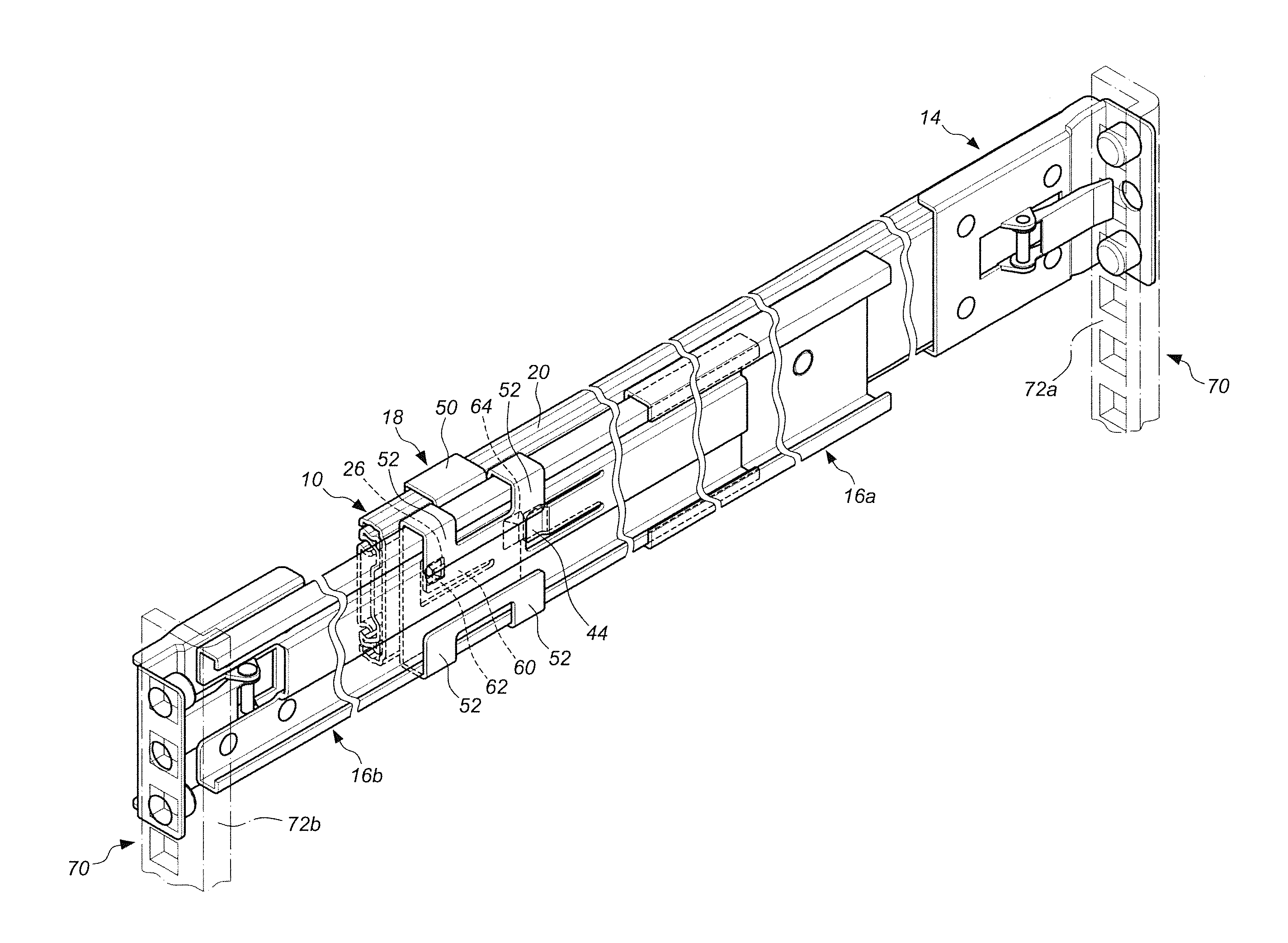
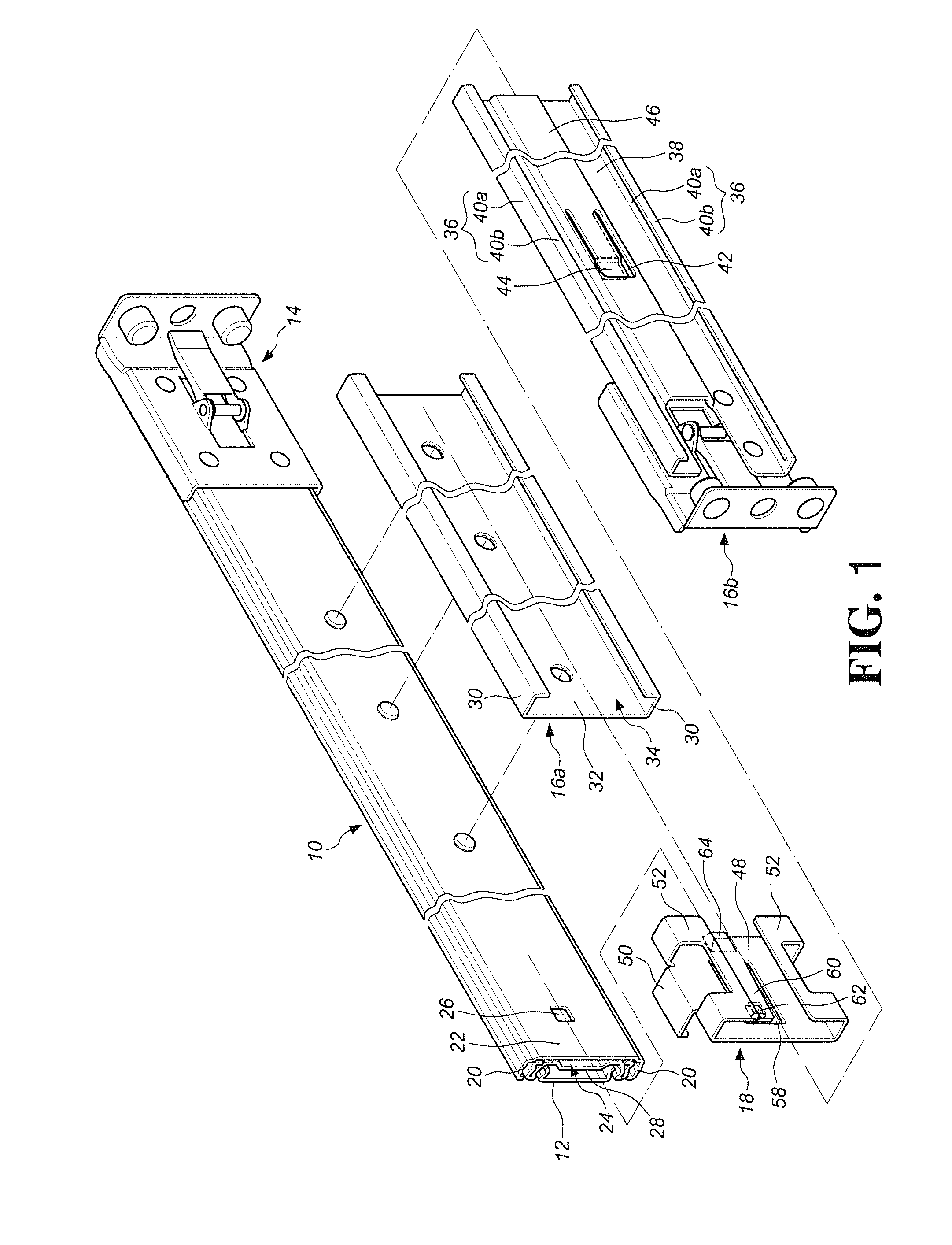
[0018]Referring to FIG. 1, the slide rail assembly of the present invention comprises an outer rail 10, an inner rail 12, a front support 14, a first rear support 16a, a second rear support 16b and a reinforcement member 18.

[0019]The outer rail 10 has a longitudinal length and two side walls 20 are connected two sides of the outer rail 10. A bridge wall 22 is connected between the two side walls 20. A longitudinal path 24 is defined between the two side walls 20 and the bridge wall 22. Preferably, an engaging hole 26 is defined through the rear end of bridge wall 22.

[0020]The inner rail 12 is slidably connected to the longitudinal path 24 of the outer rail 10. Preferably, an intermediate rail 28 is slidably connected between the inner rail 12 and the outer rail 10, so that the inner rail 12 is able to be extended to a longer distance relative to the outer rail 10 by the intermediate rail 28.

[0021]The front support 14 is connected to the front end of the outer rail 10 and secured to ...


PUM


Abstract

A slide rail assembly includes a slide assembly, a front support, a first rear support, a second rear support, and a reinforcement member. The slide rail assembly includes an outer rail, an inner rail and an intermediate rail. The front support and the first rear support are respectively connected to the front end and the outside of the outer rail. The second rear support is movably connected to the first rear support. The reinforcement member includes a body, two first support parts and at least two second support parts. The body has a slot and a contact portion. The two first support parts embrace the outer rail, and the at least two second support parts embrace the second rear support. The slide rail assembly is installed to the rack. The reinforcement member reinforces the connection between the second rear support and the outer rail.

Description

FIELD OF THE INVENTION[0001]The present invention relates to a slide rail assembly used in a rack system and a reinforcement member thereof, and more particularly, to a slide rail assembly, having a reinforcement member, whose supports are adjustable to meet requirements of maximum or minimum and to reinforce the structural strength thereofBACKGROUND OF THE INVENTION[0002]U.S. Pat. No. 8,028,965 to CHEN discloses an adjustable bracket for a slide assembly which can be installed to different depths of the racks. The amount of the adjustment of the bracket is made by the relative displacement between the cover (30) and the rear support (50). When the rear support is completely retracted to the cover, the total length of the bracket reaches its minimum length. When the rear support is pulled, relative to the cover, to its extreme position, the total length of the bracket reaches its maximum length. However, when the rear support is pulled to its extreme position, the rear support must ...

Claims


Application Information

Patent Timeline
IPC IPC(8): A47F5/10
CPCA47F5/10A47B88/43H05K7/1489E05D15/08
Inventor CHEN, KEN-CHINGYANG, SHUN-HOWANG, CHUN-CHIANG
Owner KING SLIDE WORKS CO LTD
Why Eureka
Try Eureka