Display Device
a technology of a display device and a frame portion, which is applied in the field of display devices, can solve the problems of limited frame portion width reduction and reduce the width of the frame, and achieve the effect of reducing the frame width and ensuring the rigidity of the apparatus body
- Summary
- Abstract
- Description
- Claims
- Application Information
AI Technical Summary
Benefits of technology
Problems solved by technology
Method used
Image
Examples
first modification
[0083](First Modification)
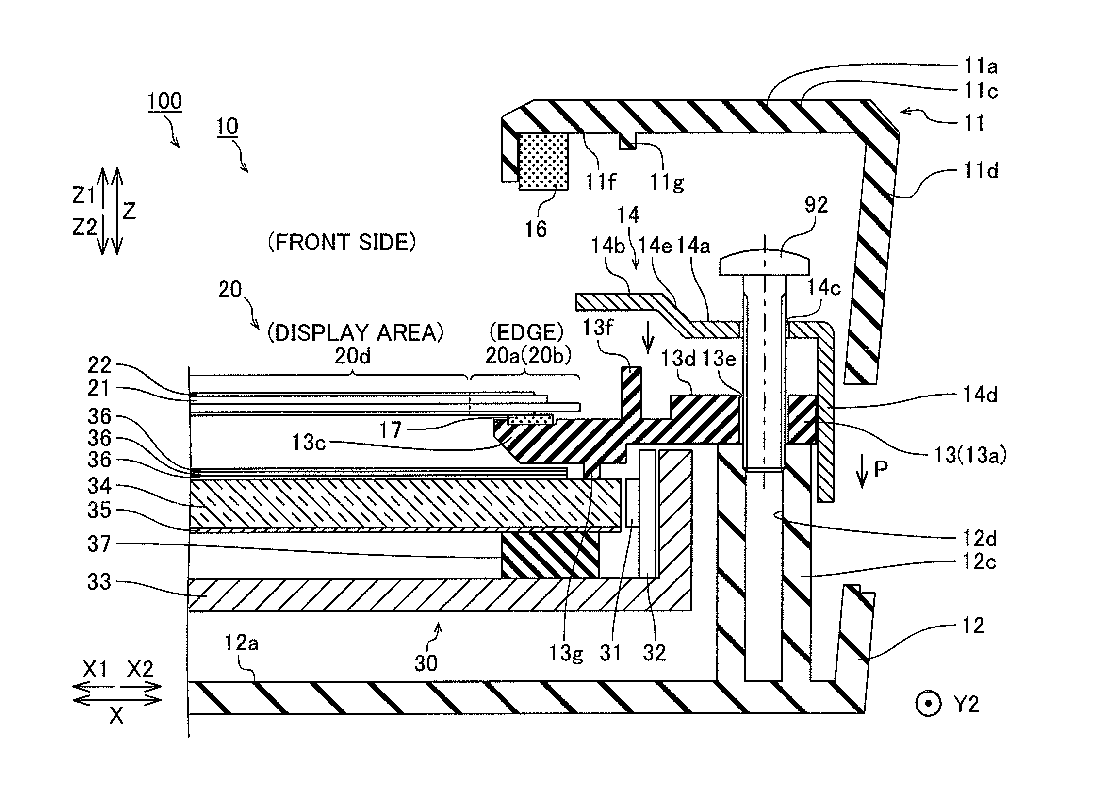
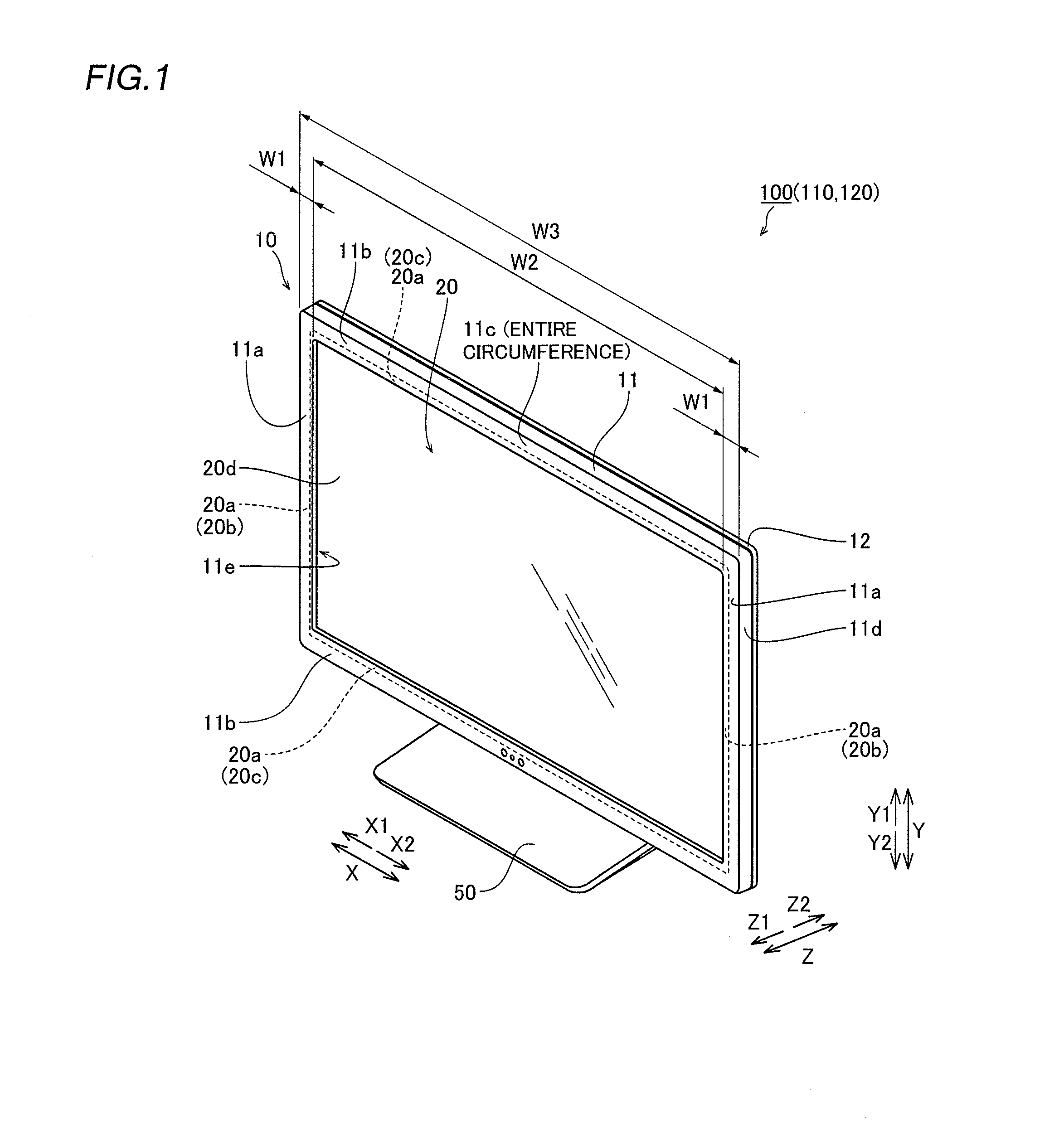
[0084]A first modification is now described with reference to FIGS. 1, 4, and 7. In this first modification, a bezel member 114 having a portion folded at about 90 degrees in an end region of an extension portion 114b is mounted on a frame member 13 (short-side frame portion 13a), as shown in FIG. 7. The bezel member 114 is an example of the “first bezel member” in the present invention. In the figure, a structure similar to that of the liquid crystal television apparatus 100 according to the aforementioned embodiment is denoted by the same reference numerals.
[0085]In a liquid crystal television apparatus 110 according to the first modification of the present invention, the bezel member 114 fixed to a fixing portion 13d of the short-side frame portion 13a is formed such that the extension portion 114b extends from a fixed portion 14a up to the vicinity of a region where a cushion member 16 is arranged along arrow X1, as shown in FIG. 7. The extension portio...
second modification
[0088](Second Modification)
[0089]A second modification is now described with reference to FIGS. 1, 4, and 8. In this second modification, a bezel member 124 having a portion on which hemming is performed in the middle of an extension portion 124b is mounted on a frame member 13 (short-side frame portion 13a), as shown in FIG. 8. The bezel member 124 is an example of the “first bezel member” in the present invention. In the figure, a structure similar to that of the liquid crystal television apparatus 100 according to the aforementioned embodiment is denoted by the same reference numerals.
[0090]In a liquid crystal television apparatus 120 according to the second modification of the present invention, the bezel member 124 fixed to a fixing portion 13d of the short-side frame portion 13a is formed such that the extension portion 124b extends along arrow X1 from a fixed portion 14a to stop short of a region where a cushion member 16 is arranged, as shown in FIG. 8. The extension portion...
PUM
| Property | Measurement | Unit |
|---|---|---|
| area | aaaaa | aaaaa |
| elastic | aaaaa | aaaaa |
| rigidity | aaaaa | aaaaa |
Abstract
Description
Claims
Application Information
 - R&D
- Intellectual Property
- Life Sciences
- Materials
- Tech Scout
- Unparalleled Data Quality
- Higher Quality Content
- 60% Fewer Hallucinations
Browse by: Latest US Patents, China's latest patents, Technical Efficacy Thesaurus, Application Domain, Technology Topic, Popular Technical Reports.
© 2025 PatSnap. All rights reserved.Legal|Privacy policy|Modern Slavery Act Transparency Statement|Sitemap|About US| Contact US: help@patsnap.com


