Solar Powered Ground Light

a ground light and solar energy technology, applied in fixed installations, lighting and heating equipment, with built-in power, etc., can solve the problems of insufficient use of ground or in-deck support to provide passive lighting, wear of pedestrian traffic, wiring and providing lighting in places, etc., to reduce the duty cycle and no power resource expenditure

Inactive Publication Date: 2014-08-07
HERMAN N PHILHOWER AS TRUSTEE OF THE H N PHILHOWER FAMILY TRUST LAST DATED OCTOBER 31 2012
View PDF2 Cites 29 Cited by
  • Summary
  • Abstract
  • Description
  • Claims
  • Application Information

AI Technical Summary

Benefits of technology

[0025]During daylight hours and periods of good visibility, solar powered ground lights physical presence are easy to see even when turned off. These structures are attractive, decorative, and clearly indicate the expected location of paths or boundaries. During periods of darkness and periods of poor visibility it is difficult or even impossible to see the path or objects in the area, the solar powered ground lights will afford a much needed light reference. When lighting cannot be used, a person could wander off the path and trip and fall. A solar powered illuminated ground light system provides for easy visibility to address the concerns for safety and providing an easy way to determine the location of th...

Problems solved by technology

In-ground or in-deck support is not utilized enough to provide passive lighting.
These types of lighting are inappropriate for high traffic areas where the object of providing lighting and being not significantly obstructive to walking is desired.
Some illumination systems are solar powered and temporary with housing that are thrust into the ground with a steak and are not capable of being mounted into a surface or mounted to as to permit and illuminate pedestrian traffic.
Another issue for pedestrian traffic is wear.
Many potentially dangerous places to walk are not lighted because the expense of wiring and providing lighting in places not heavily frequented by pedestrians is not believed to be justified.
However, in a harbor environment lighting is c...

Method used


Image

  • Solar Powered Ground Light
  • Solar Powered Ground Light
  • Solar Powered Ground Light

Examples


Embodiment Construction

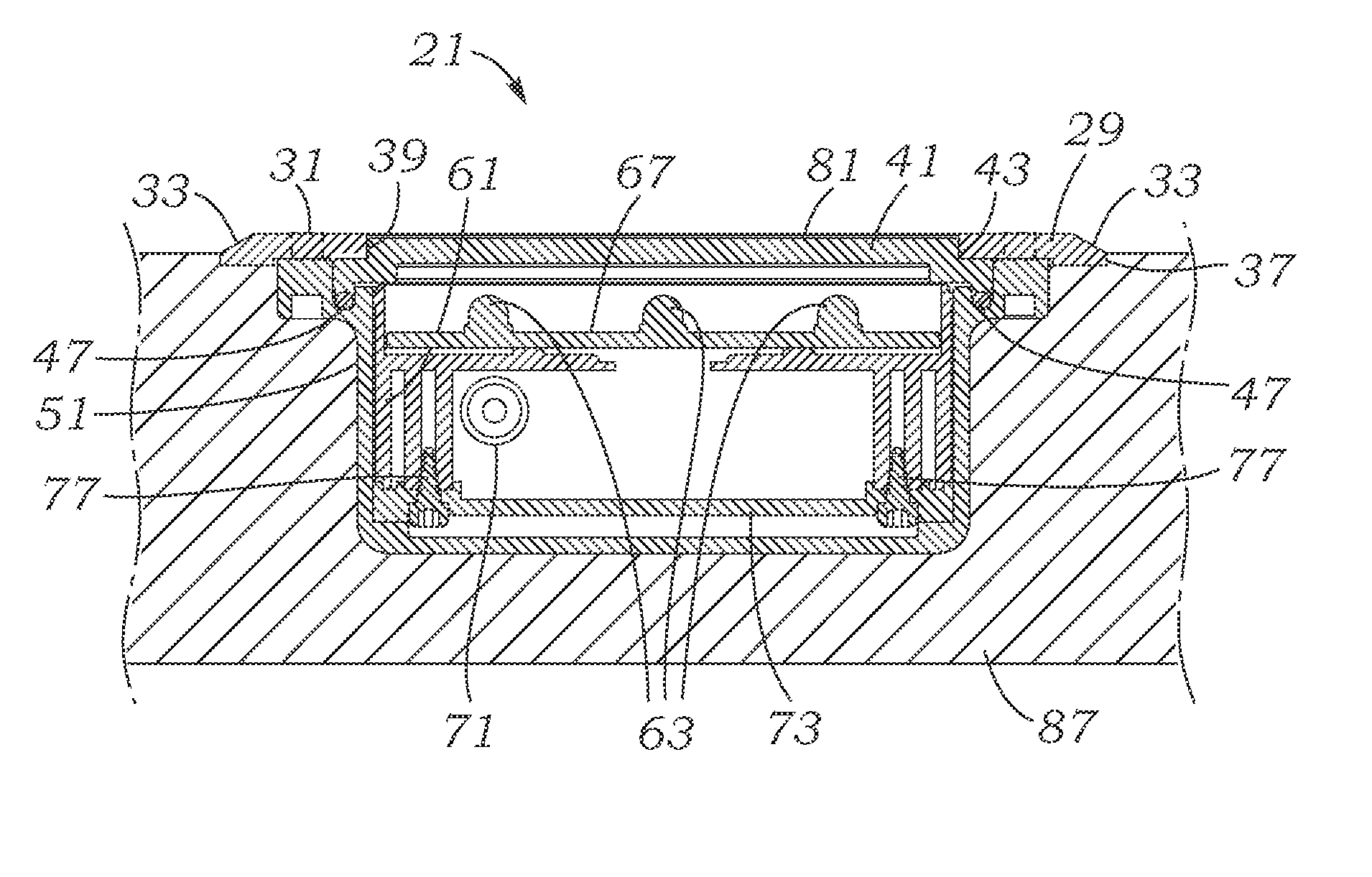
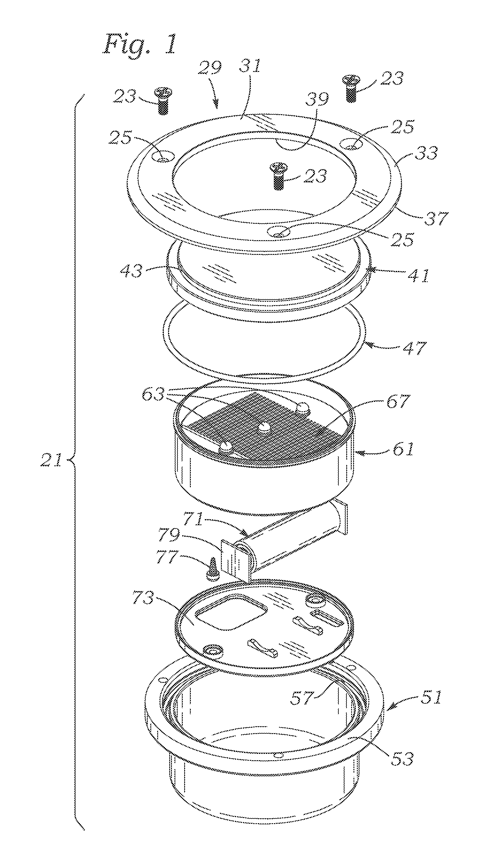
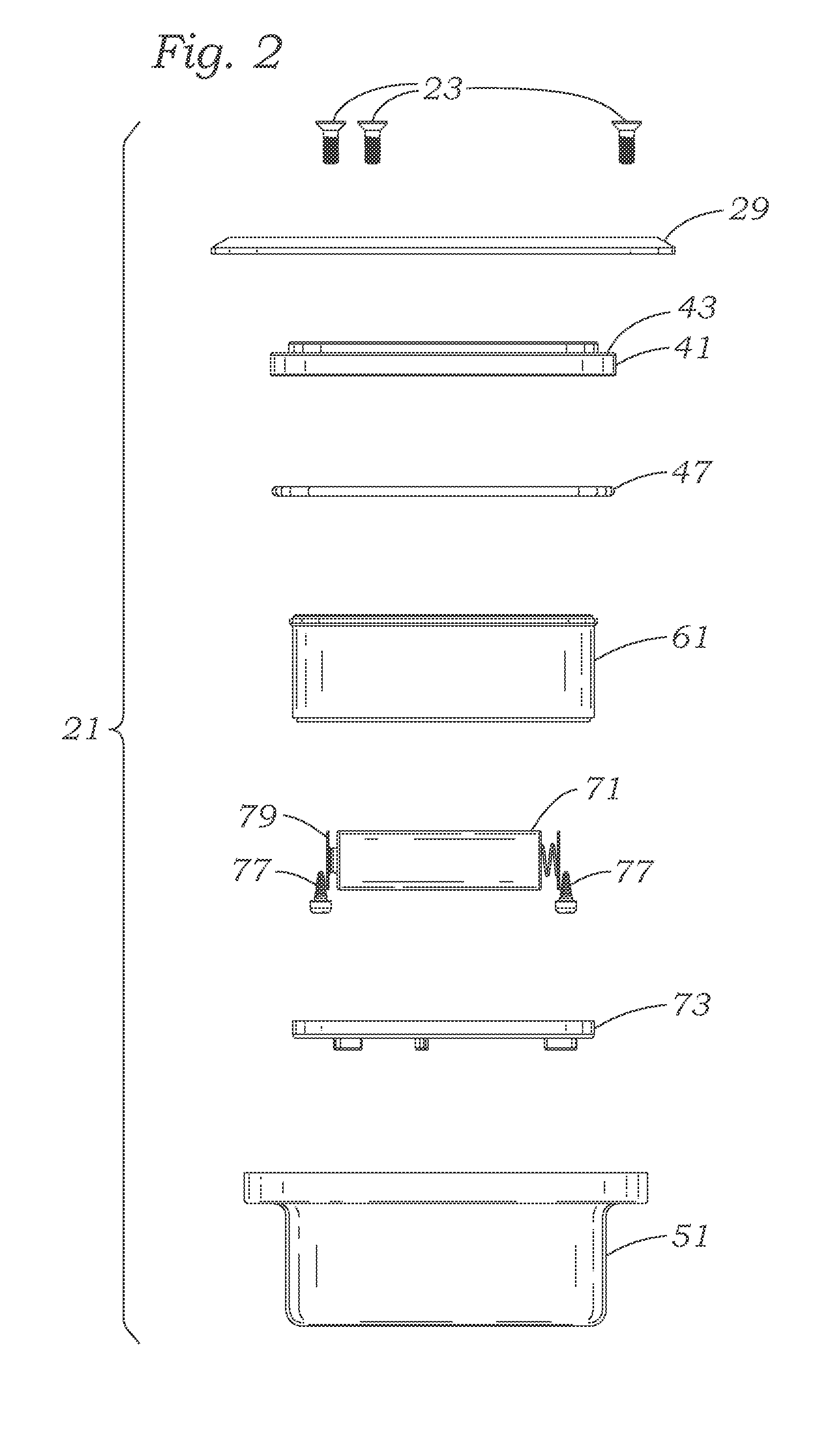
[0036]Referring to FIG. 1, a plan view looking into a solar powered ground light 21 of the invention illustrates the interfitting and spatial relationships of assembly and construction. A series of three mounting screws 23 are designed to pass through associated apertures 25 of a top mounting ring 29. The number of screws 23 and the number of apertures 25 may vary, it is believed that three will give an acceptable engagement and force sharing relationship. The top mounting ring 29 has a main planar surface 31, a bevel surface 33 located circumferentially outside the main planar surface 31 and oriented circumferentially outward and upward with respect to the main planar surface 31. Beneath the bevel surface 33 is an abbreviated outer annular surface 37. The abbreviated outer annular surface 37 may be covered by providing a shallow chamfer in the surface into which the solar powered ground light 21 may be installed, so that the outermost part of the bevel surface 33 may be even with, ...


PUM


Abstract

A solar powered ground lights is typically mounted in a walkway, pathway, pool deck, roadway, park pathway, either in cement, wood, synthetic materials, or otherwise, and are ideally suited for use in walls, ceilings, and pool or dock areas because they are readily mounted from the top, requiring only a cylindrical depression and possibly three screws for mounting and require no external wiring. The solar powered ground lights are also low voltage and safe. Illumination of the Solar powered ground lights is provided by a Solar Powered system utilizing Light Emitting Diodes (LEDs), or an electro-illuminescent Lighting system backed up with a solar powered circuit for the rechargeable battery. This provides for an illumination system capable if providing ease if view for pedestrians as well as illuminating roadways. The system may be fully IP68 waterproof rated.

Description

[0001]Continuation of Provisional Patent No. 61 / 760,617 filed Feb. 4, 2013.FIELD OF THE INVENTION[0002]The present invention relates to improvements in the field of ground mounted support structures for providing stable support and for providing illumination in a manner that is low maintenance and with automatic operational service, and especially lights which are ground, dock, deck, boat deck and walk mounted which will provide passive and low maintenance illumination by providing a constant night time illumination without the need for wiring, and especially in a harsh marine environment.BACKGROUND OF THE INVENTION[0003]In-ground or in-deck support is not utilized enough to provide passive lighting. Some types of ground lighting are known for gardens and which is supported on short pikes to give a high lighting effect with lateral light directed upon plants and garden areas. These types of lighting are inappropriate for high traffic areas where the object of providing lighting and ...

Claims


Application Information

Patent Timeline
IPC IPC(8): F21S9/03F21S8/00F21V31/00
CPCF21S9/037F21V31/00F21S8/032F21S8/022F21V31/005F21Y2115/10
Inventor ADAIR, ROBIN CHARLES
Owner HERMAN N PHILHOWER AS TRUSTEE OF THE H N PHILHOWER FAMILY TRUST LAST DATED OCTOBER 31 2012
Why Eureka
Try Eureka