
Heat gun head

a heat gun and head technology, applied in the field of heat gun head configuration, can solve the problem of evenly distributing hea

Inactive Publication Date: 2014-08-07
HONG FU JIN PRECISION IND (SHENZHEN) CO LTD +1
View PDF3 Cites 7 Cited by
  • Summary
  • Abstract
  • Description
  • Claims
  • Application Information

AI Technical Summary

Benefits of technology

The present patent is about a heat gun head with a unique configuration that can melt soldering tins evenly on a chip. The heat gun head has a housing with a tapered head, rotatably connected blocks, and a hollow columnar neck. The housing has a recess with openings and pivot holes for a motion mechanism. The heat gun head also includes a transmission mechanism with a transmission pole, gears, and an operation pole. The technical effect of the invention is to provide a heat gun head with improved heating efficiency and uniformity for soldering chips.

Problems solved by technology

However, the different distances between the pins and the outlet lead to that the pins do not obtain the heat evenly, melted soldering tin at one of the pins may have been re-solidified meanwhile the soldering tin at the other pin is still being melted, which is inconvenient.

Method used


Image

  • Heat gun head
  • Heat gun head
  • Heat gun head

Examples


Embodiment Construction

[0009]The disclosure, including the accompanying drawings, is illustrated by way of example and not by way of limitation. It should be noted that references to “an” or “one” embodiment in this disclosure are not necessarily to the same embodiment, and such references mean “at least one.”

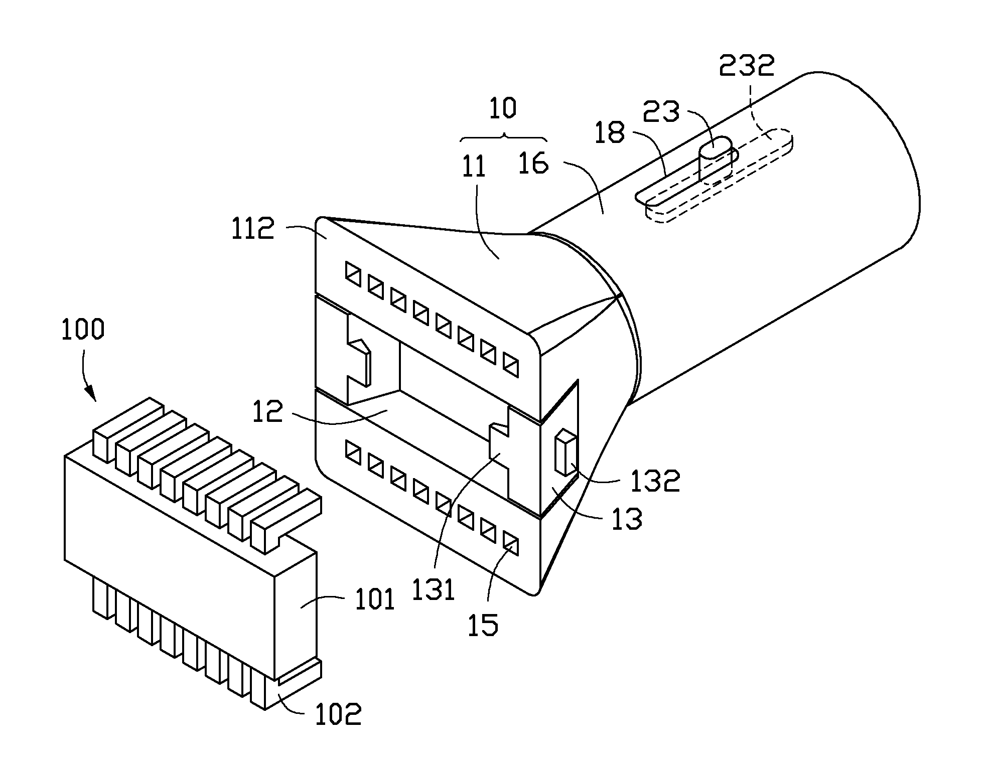
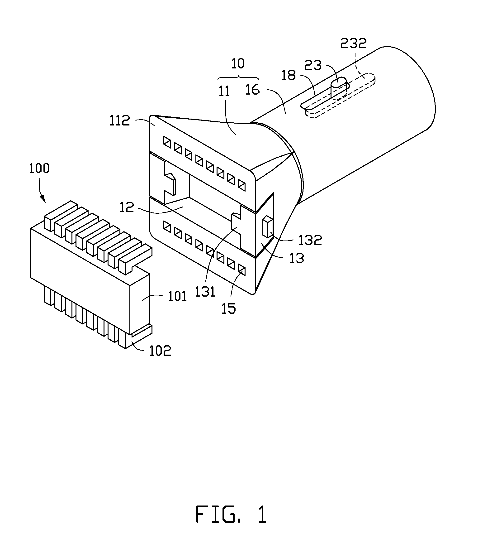
[0010]FIGS. 1-3 show an exemplary embodiment of a heat gun head of a heat gun. The heat gun head is provided to detach a soldered chip 100 from a circuit board. The chip 100 includes a main body 101, and a plurality of pins 102 extending down from opposite sides of the main body 101. The heat gun head includes a housing 10, a transmission mechanism 20, and a motion mechanism 30.

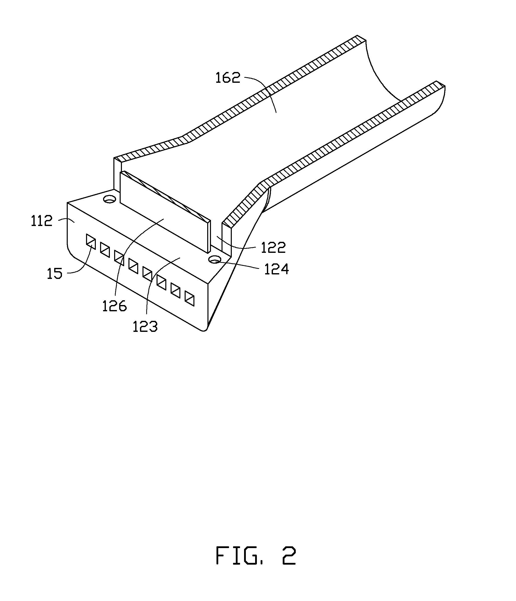
[0011]The housing 10 includes a hollow tapered head 11, two blocks 13 rotatably connected to the head 11, and a hollow columnar neck 16 connected to a small rear end of the head 11. A recess 12 is defined in a large front end of the head 11 opposite to the neck 11, extending through opposite sides and a front end surface 112 o...


PUM


Abstract

A heat gun head includes a housing. The housing defines two rows of outlets in a front end surface of the housing. When the heat gun head operates, hot air in the housing flows out of the housing through the two rows of outlets.

Description

BACKGROUND[0001]1. Technical Field[0002]The present disclosure relates to the configuration of a heat gun head.[0003]2. Description of Related Art[0004]A heat gun head generally has only one outlet. Hot air flows from the outlet of the heat gun head to heat opposite sides of a chip in turn, to melt soldering tins attached to pins at opposite sides of the chip, so that the chip can be disengaged from a circuit board easily. However, the different distances between the pins and the outlet lead to that the pins do not obtain the heat evenly, melted soldering tin at one of the pins may have been re-solidified meanwhile the soldering tin at the other pin is still being melted, which is inconvenient.BRIEF DESCRIPTION OF THE DRAWINGS[0005]Many aspects of the present embodiments can be better understood with reference to the following drawings. The components in the drawings are not necessarily drawn to scale, the emphasis instead being placed upon clearly illustrating the principles of the...

Claims


Application Information

Patent Timeline
IPC IPC(8): F24H3/04
CPCF24H3/0423
Inventor MA, SONGZHOU, WUXIAO, GUI-FUPANG, WEI
Owner HONG FU JIN PRECISION IND (SHENZHEN) CO LTD
Learn More