
Film laminating mechanism

A technology of film sticking mechanism and pressing mechanism, which is applied in packaging and other directions, and can solve the problems such as inconvenient cutting of film tapes

Pending Publication Date: 2021-02-19
LAPLACE (WUXI) SEMICON TECH CO LTD
View PDF0 Cites 2 Cited by
  • Summary
  • Abstract
  • Description
  • Claims
  • Application Information

AI Technical Summary

Problems solved by technology

[0004] Therefore, the technical problem to be solved by the present invention is to overcome the defects of inconvenient cutting of the film tape in the prior art, thereby providing a film sticking mechanism

Method used


Image

  • Film laminating mechanism
  • Film laminating mechanism

Examples


Embodiment Construction

[0017] In order to make the object, technical solution and advantages of the present invention more clear, the present invention will be further described in detail below in conjunction with the accompanying drawings and embodiments. It should be understood that the specific embodiments described here are only used to explain the present invention, not to limit the present invention.

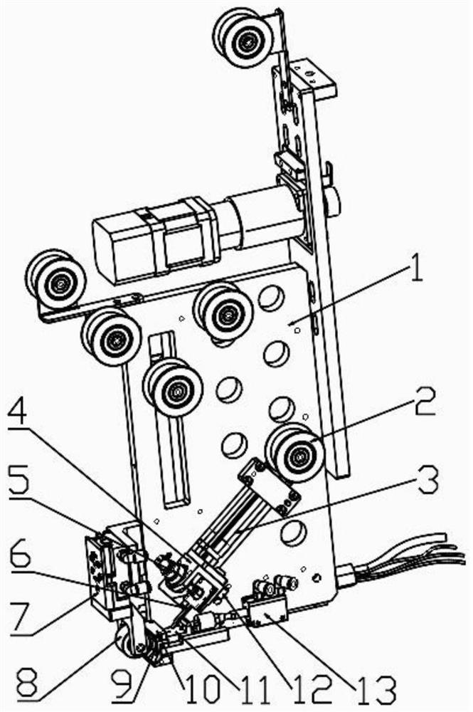
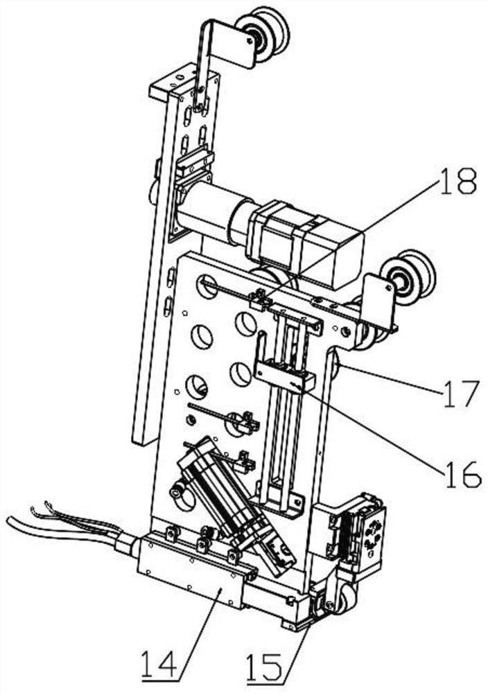
[0018] A film sticking mechanism, which includes a fixed plate 1, the fixed plate 1 is arranged as a cuboid plate, and the fixed plate 1 is provided with a film tape guide assembly 2, a film tape pressing mechanism, an installation frame 4, a film tape buffer assembly and Cutter assembly, the film strip guide assembly 2 is used to guide the film strip, the film strip pressing mechanism is used to straighten the film strip, and the installation frame 4 is used to press the film strip The tightening assembly is fixedly arranged, and the film tape buffering assembly is used to realize the buffering...


PUM


Abstract

The invention relates to the technical field of photovoltaic module production equipment, in particular to a film laminating mechanism which aims at solving the problem that in the prior art, a film belt is inconvenient to cut. The film laminating mechanism is technically characterized by comprising a fixing plate which is a cuboid plate, wherein a film belt guide assembly, a film belt pressing mechanism, a mounting frame, a film belt temporary storage assembly and a cutter assembly are arranged on the fixing plate, the film belt guide assembly is used for guiding the film belt, the film beltpressing mechanism is used for straightening the film belt, the mounting frame is used for fixedly arranging the film belt pressing assembly, a hot air gun assembly and an air outlet are further arranged at the bottom of the fixing plate, and the hot air gun assembly and the air outlet are fixedly arranged. Through arrangement of the hot air gun assembly, hot air is conveyed to the air outlet, sothat the film belt can be conveniently cut off; and meanwhile, through the arrangement of air blowing assemblies, the situation that the film belt deforms due to the influence of the ambient temperature is avoided.

Description

technical field [0001] The invention relates to the technical field of photovoltaic module production equipment, in particular to a film sticking mechanism. Background technique [0002] The structure of the traditional photovoltaic module from the back to the front is the backplane 1, the encapsulation film 2, the battery sheet 3, the encapsulation film 2, and the glass plate 4; there is a gap of 1mm-4mm between the sheets and strings of the battery sheets. The gaps occupy 2%-4% of the area of ​​photovoltaic modules, and the light energy irradiated into these gaps is difficult to be directly absorbed or utilized. At present, the photovoltaic industry uses reflective backplanes instead of backplanes or reflective white EVA instead of encapsulation films to utilize the light energy in these gaps to improve light energy utilization. [0003] During the film sticking process, because the film tape has a certain toughness, it is difficult to cut it off. Contents of the invent...

Claims


Application Information

Patent Timeline
IPC IPC(8): B65B33/02B29C63/02
CPCB29C63/02B65B33/02
Inventor 林佳继戴佳裴维维葛炜杰安志强马力
Owner LAPLACE (WUXI) SEMICON TECH CO LTD
Learn More