Antenna reflector apparatus

a technology of reflectors and antennas, applied in the direction of antennas, antenna details, waveguide horns, etc., can solve the problems of long-term efforts, inability to transmit and receive data, and limited 60 ghz band, etc., and achieve the effect of increasing the signal gain of the feed antenna

Inactive Publication Date: 2014-08-14
SJ ANTENNA DESIGN
View PDF5 Cites 16 Cited by
  • Summary
  • Abstract
  • Description
  • Claims
  • Application Information

AI Technical Summary

Benefits of technology

[0010]The present invention is related to antenna reflector apparatus, which comprises a horn-shaped reflector indentation as a reflection device of a feed antenna for increasing signal gain of the feed antenna.

Problems solved by technology

If antenna is absent, wireless communication system is not capable of transmitting and receiving data.
Because electromagnetic energy in 60 GHz band configured to carry high speed audio / video transmission of future mobile communication device is easily absorbed by oxygen particles in the atmosphere, 60 GHz band is limited to short range (less than 10 meters) wireless transmission.
However, most of reflectors used in current mobile devices belong to plane reflector or flat reflector which increases reflected energy of broadside radiation patterned antenna only but does nothing with reflected energy of end-fired radiation patterned antenna.
In order to solve these problems, efforts have long been made in vain, while ordinary products and methods offering no appropriate structures and methods.

Method used


Image

  • Antenna reflector apparatus
  • Antenna reflector apparatus
  • Antenna reflector apparatus

Examples


Embodiment Construction

[0017]Some embodiments of the present invention are described in details below. However, in addition to the descriptions given below, the present invention can be applicable to other embodiments, and the scope of the present invention is not limited by such, rather by the scope of the claims. Moreover, for better understanding and clarity of the description, some components in the drawings may not necessary be drawn to scale, in which some may be exaggerated relative to others, and irrelevant parts are omitted.

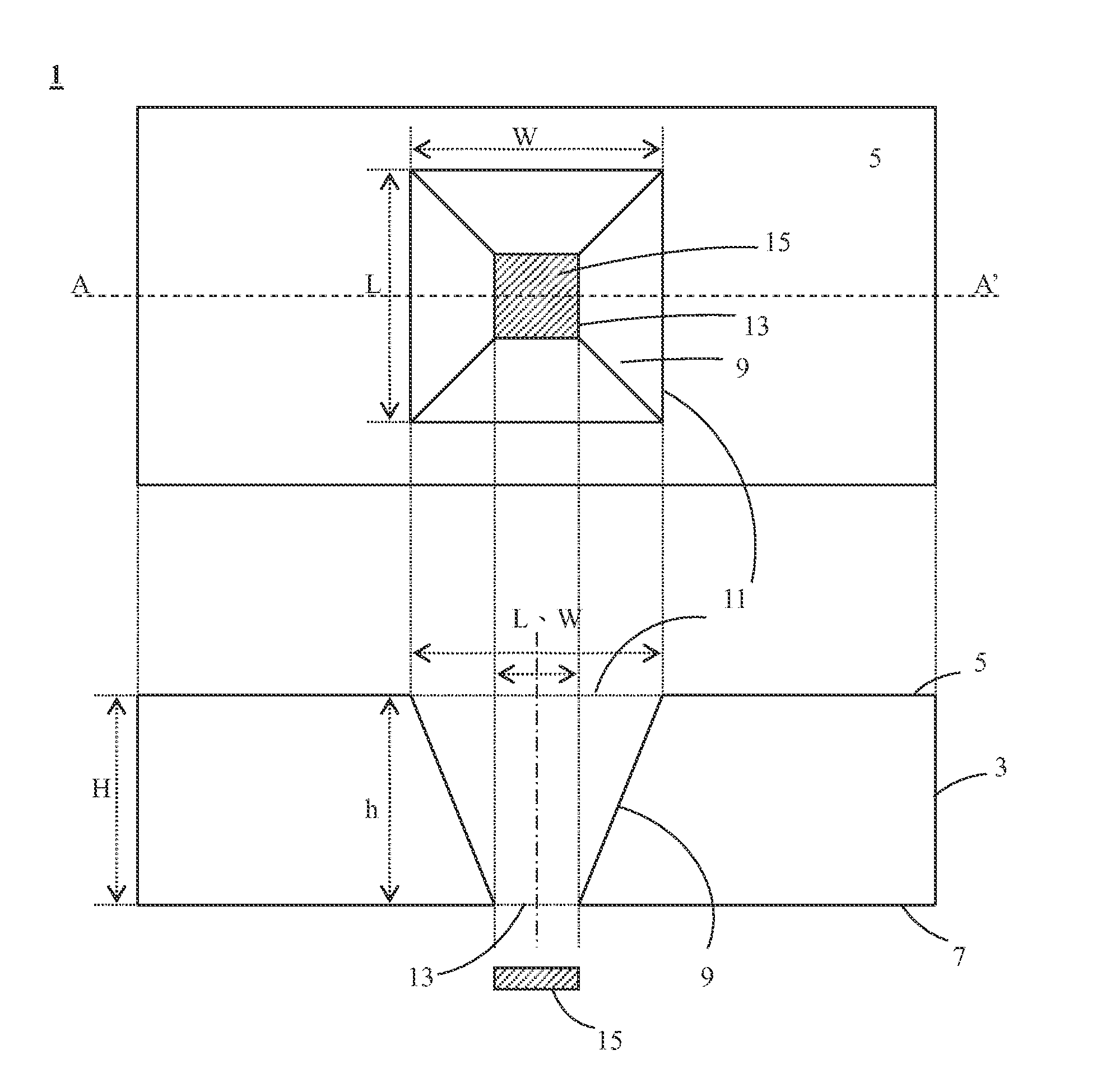
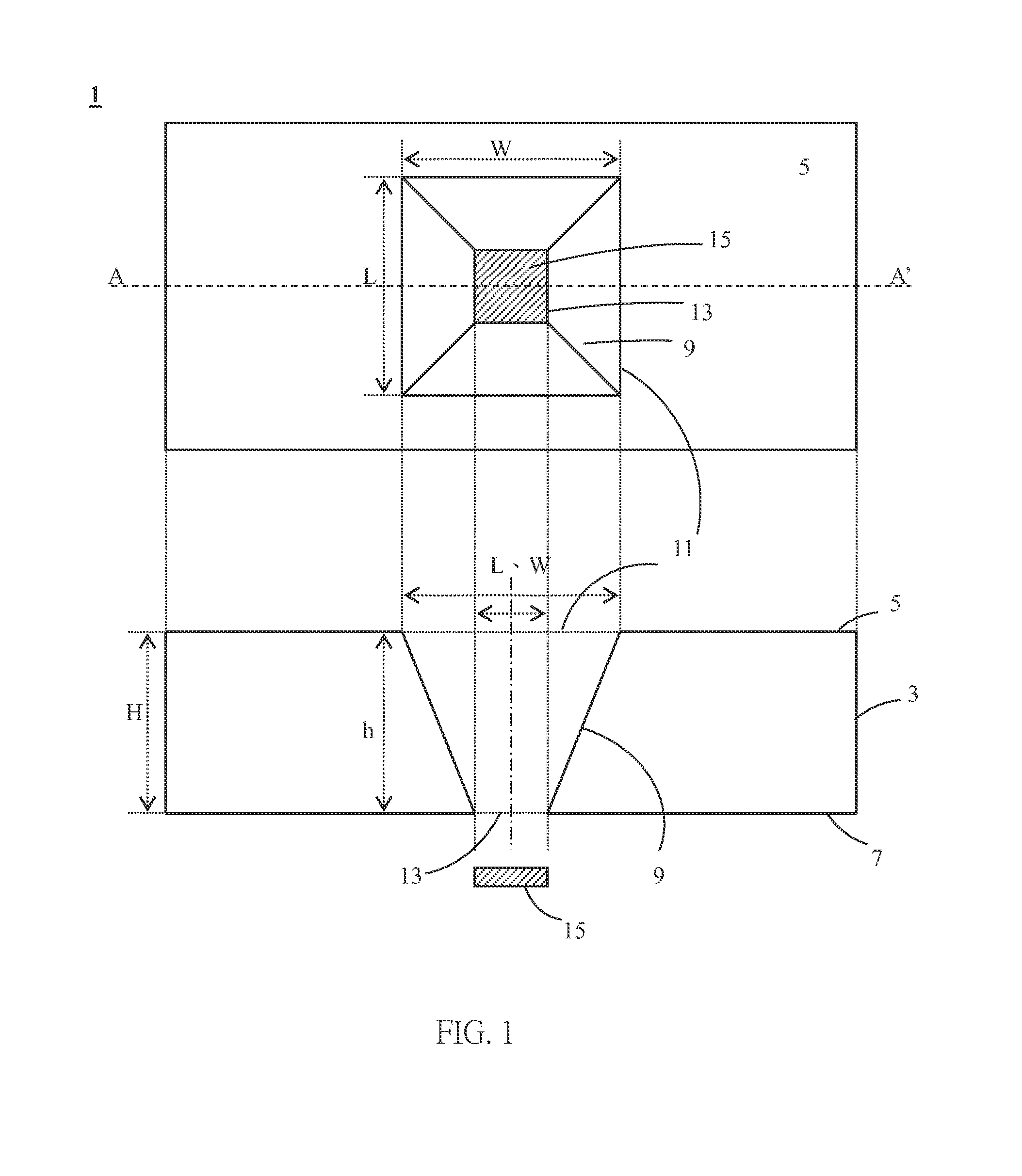
[0018]Please refer to FIG. 1, which is a top view diagram of an antenna reflector apparatus in accordance with an embodiment of the present invention and a cross sectional view diagram corresponding to a section line A-A′. As shown in the FIG. 1, the antenna reflector apparatus 1 includes a shell body 3, a reflector indentation 9, and an antenna 15. The shell body 3 has a first surface 5 and a second surface 7 opposite to the first surface 5. The material of the shell body 3 i...


PUM


Abstract

According to one aspect of the present invention, an antenna reflector apparatus provided comprises a shell body, a reflector indentation, and an antenna. The reflector indentation embedded in the shell body comprises a first indentation opening and a second indentation opening opposite to the first indentation opening. The first indentation opening is on the first surface of the shell body; the second indentation opening is on the second surface of the shell body. And the first indentation opening penetrates the shell body and connects to the second indentation opening. The antenna is located besides the second indentation opening of the reflector indentation. The area of the first indentation opening of the reflector indentation is larger than the area of the second indentation opening.

Description

CROSS REFERENCE TO RELATED APPLICATIONS[0001]This application claims priority under 35 U.S.C 119 to Taiwan patent application No. 102105468, filed on Feb. 8, 2013, the disclosure of which is incorporated herein by reference.BACKGROUND OF THE INVENTION[0002]1. Field of the Invention[0003]The present invention relates to antenna reflector apparatus, and more particularly, to reflector apparatus which increase signal gain of feed antenna.[0004]2. Description of the Prior Art[0005]While wireless communication systems become more and more popular, wireless communication function is required at more and more applications in order to satisfy consumers' needs. Antenna is an important component used for transmitting and receiving electromagnetic wave in wireless communication system. If antenna is absent, wireless communication system is not capable of transmitting and receiving data. Therefore, antenna is a key component to system performance.[0006]Because electromagnetic energy in 60 GHz b...

Claims


Application Information

Patent Timeline
Patent Type & Authority Applications(United States)
IPC IPC(8): H01Q19/10
CPCH01Q19/10H01Q1/243H01Q13/02
Inventor YU, YA-CHUNG
Owner SJ ANTENNA DESIGN
Why Eureka
Try Eureka