Unlock instant, AI-driven research and patent intelligence for your innovation.

Projection system, image generating method, and computer-readable storage medium

a projection system and image generating technology, applied in the direction of instruments, computing, electric digital data processing, etc., can solve the problems of user operations on projection devices that cannot be detected, and may occur the above-described problems

Inactive Publication Date: 2014-08-14
RICOH KK
View PDF15 Cites 8 Cited by
  • Summary
  • Abstract
  • Description
  • Claims
  • Application Information

AI Technical Summary

Benefits of technology

The present invention aims to solve problems in conventional technology. The invention provides a projection system that can detect user operations on an image and project the image onto a surface. The system can also capture an image of the image-capturing area and calculate the coordinates of the image-capturing area based on the captured image and the projected image when any user operation is detected. The system can then determine the position of the target image in the projected image and generate a new projected image in which the target image is laid out on the determined position. The invention also includes a projection control unit to control the projection unit. Overall, the invention allows for easier and more precise projection of images onto surfaces.

Problems solved by technology

In the conventional technologies, however, some user operations on projection devices cannot be detected.
Specifically, if a projection device is operated by recognizing a user action by a camera and if an image-capturing area in which the camera can capture images is smaller than the projected image, some operations on the projection device cannot be detected.
That is, when using a projection device for the purpose of presentation or display of content information and if no sufficient distance between the surface for projection and the camera can be ensured, the above-described issue may occur.

Method used


Image

  • Projection system, image generating method, and computer-readable storage medium
  • Projection system, image generating method, and computer-readable storage medium
  • Projection system, image generating method, and computer-readable storage medium

Examples


first embodiment

System Configuration

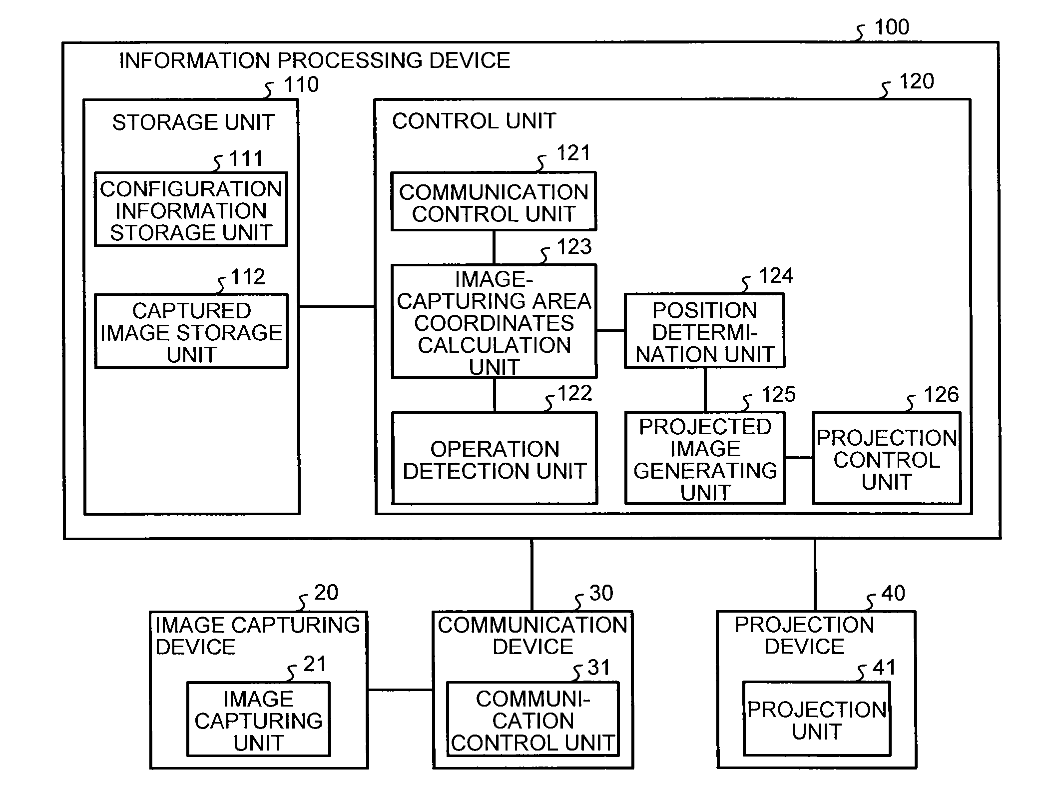
[0038]The following describes a configuration of a projection system according to a first embodiment of the present invention with reference to FIG. 1. FIG. 1 is a diagram illustrating a configuration example of a projection system according to the first embodiment.

[0039]As illustrated in FIG. 1, a projection system 10 includes an image capturing device 20, a communication device 30, a projection device 40, and an information processing device 100. The image capturing device 20 is a camera or the like that captures an image for projection, i.e., projected images projected on a surface for projection and generates a captured image. The image capturing device 20 is coupled to the communication device 30. The area in which the image capturing device 20 can capture images may be referred to as an “image-capturing area”, hereinafter. The image-capturing area has various sizes depending on the distance between the image capturing device 20 and the surface for projectio...

second embodiment

[0067]In the above-described the first embodiment, the vertex coordinates of the button image when the center of gravity of the button image is superimposed onto the center of gravity of the image-capturing area are obtained, thereby determining the position of the button image in the projected image. In a second embodiment, the following describes determination of the position of the button image in the projected image when the size of the button image is larger than the image-capturing area.

[0068]Configuration of Device According to Second Embodiment

[0069]The following describes a configuration of a device according to the second embodiment with reference to FIG. 5. FIG. 5 is a functional block diagram illustrating a configuration example of the device according to the second embodiment. In the second embodiment, common numerals are assigned to similar components to the first embodiment, and overlapping explanation thereof may be omitted. Specifically, the functions, configuration...

third embodiment

[0086]In the above-described first and second embodiments, determination of the position of the button image in the projected image is described when a single button image is provided. In a third embodiment, the following describes determination of the positions of button images in the projected image when a plurality of button images is provided.

[0087]Configuration of Device According to Third Embodiment

[0088]The following describes a configuration of a device according to the third embodiment with reference to FIG. 8. FIG. 8 is a functional block diagram illustrating a configuration example of the device according to the third embodiment. In the third embodiment, common numerals are assigned to similar components to the first embodiment, and overlapping explanation thereof may be omitted. Specifically, the functions, configurations, and processes for the components in the third embodiment are the same as those for the components in the first embodiment except for a position determ...


PUM


Abstract

A projection system includes a projection unit configured to project a projected image on a surface for projection; an image capturing unit configured to capture an image of an image-capturing area representing an area; an operation detection unit configured to detect any user operation on an operation target image representing a targeted image for the user operation by using the captured image; a calculation unit configured to calculate image-capturing area coordinates for specifying a position of the image-capturing area in the projected image based on the captured image and the projected image; a position determination unit configured to determine a position of the operation target image in the projected image based on the image-capturing area coordinates; and a projected image generating unit configured to generate a projected image in which the operation target image is laid out on the determined position.

Description

CROSS-REFERENCE TO RELATED APPLICATIONS[0001]The present application claims priority to and incorporates by reference the entire contents of Japanese Patent Application No. 2013-023632 filed in Japan on Feb. 8, 2013.BACKGROUND OF THE INVENTION[0002]1. Field of the Invention[0003]The present invention relates to a projection system, an image generating method, and a computer-readable storage medium.[0004]2. Description of the Related Art[0005]Conventional technologies for operating projection devices have been known, in which a pointing position is moved using a pointing device such as an electronic pen on a projected image projected on the surface for projection such as a screen by projection devices such as a projector. By contrast, with some technologies, projection devices can be operated without using a pointing device. For example, a technology has been known, in which a predetermined action of a user, i.e., a gesture is recognized by a camera and the operation corresponding to...

Claims


Application Information

Patent Timeline
IPC IPC(8): G06F3/042
CPCG06F3/0425G06F3/011G06F3/0304
Inventor FUJIKAWA, KAZUYAISOZAKI, TOSHIHIROTANABE, KAZUHIDESUGINO, MAKOTOKOBAYASHIYAMAMOTO, RYOUJI
Owner RICOH KK