Coupling device and method for using the same

a coupling device and self-sealing technology, applied in the direction of intravenous devices, catheters, other medical devices, etc., can solve the problems of affecting the operation efficiency of the patient, affecting the safety of patients, and requiring a large amount of operator time for conventional connectors and couplings

Active Publication Date: 2014-08-14
MAQUET CARDIOPULMONARY GMBH
View PDF9 Cites 9 Cited by
  • Summary
  • Abstract
  • Description
  • Claims
  • Application Information

AI Technical Summary

Benefits of technology

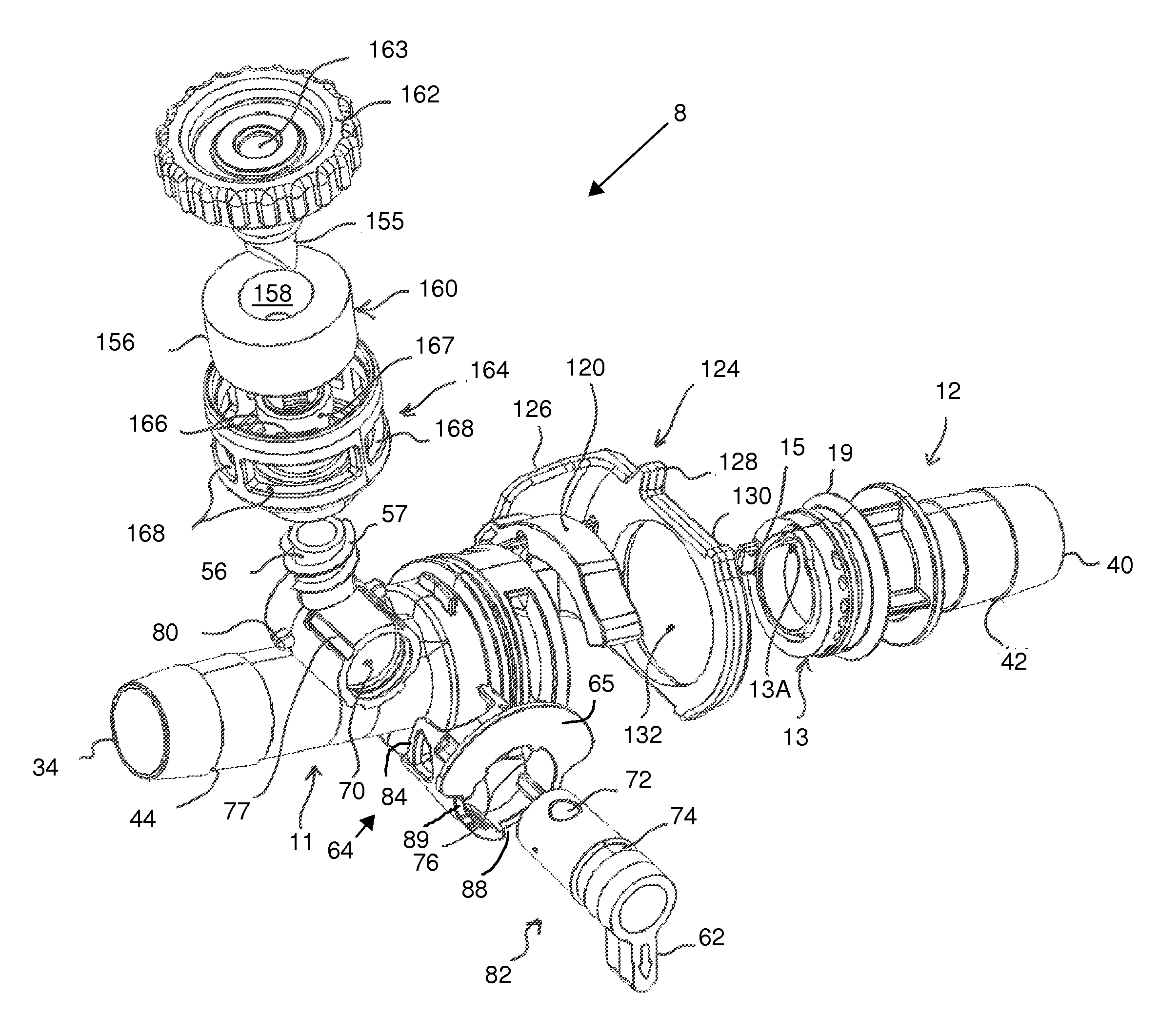
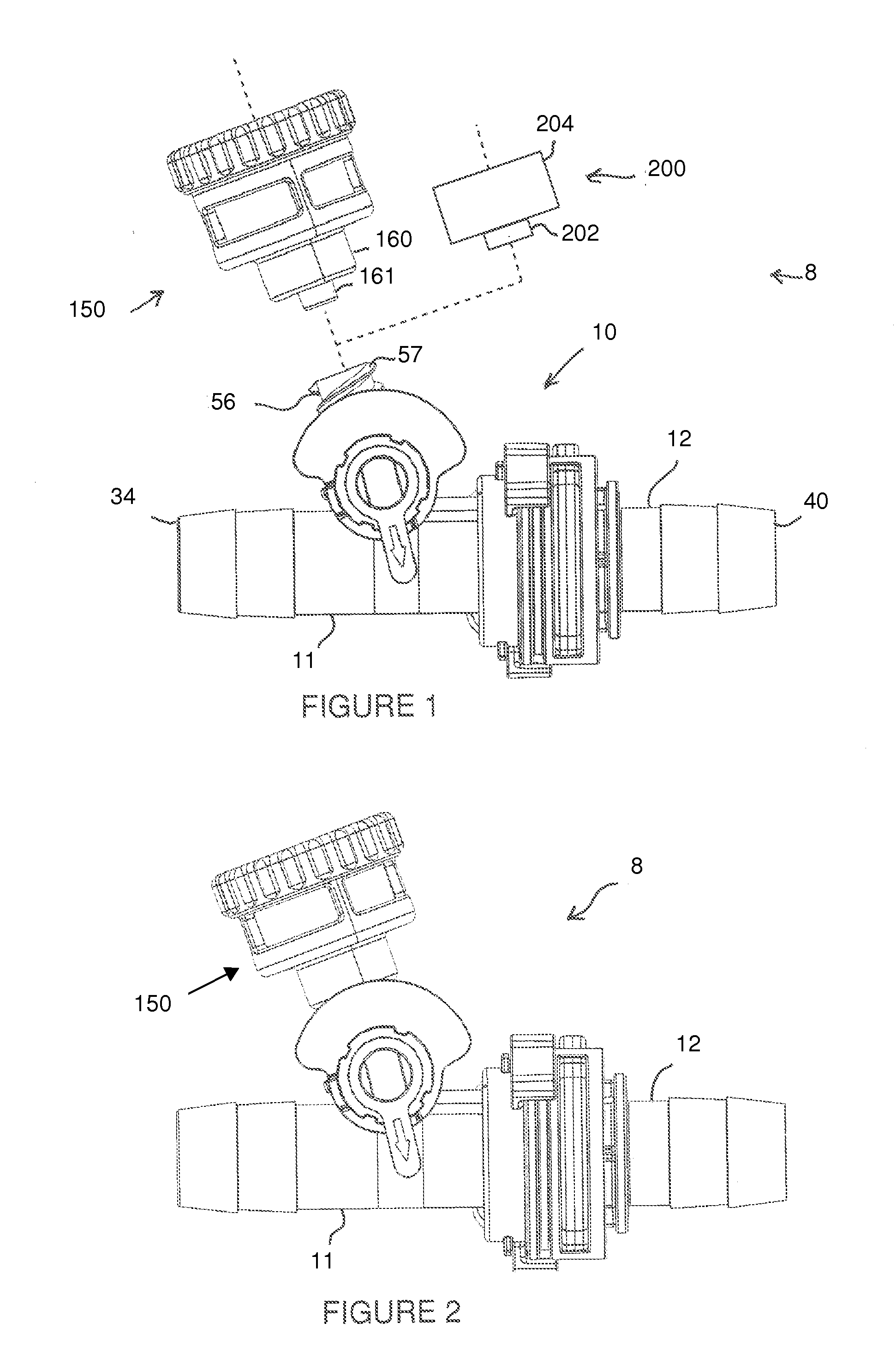
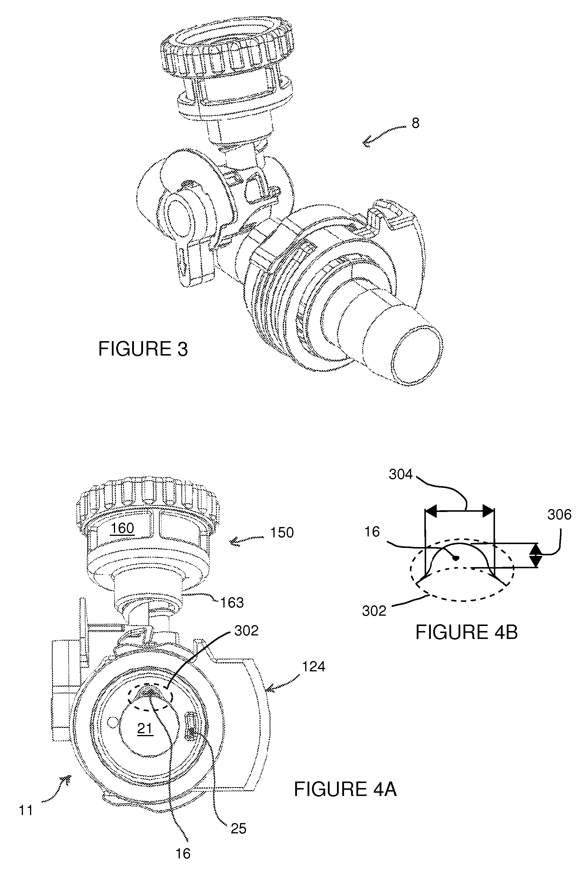
[0010]To solve the above-described problems, embodiments of the present invention and disclosure provide a quick-release and / or self-sealing coupling device and assembly useful for flexible fluid carrying conduits, hoses or pipe lines, in particular for the types used in extracorporeal blood circulation systems and circuits.

Problems solved by technology

If not performed properly or carefully, the exchange of components may place the patient at risk for one or more complications.
Conventional connectors and couplings require a relatively large amount of operator time to carefully separate and connect new components to a blood circuit.
Occasionally an actual separation of a connected hose may accidentally occur and require user intervention to reconnect the coupling.
Conventional non-medical couplings such as the quick-release coupling embodiment shown in U.S. Pat. No. 5,052,725 to Meyer et al. are not suitable for certain medical applications.
The clearance between the male and female coupling members is relatively large, so that a gap is formed which may trigger or contribute to a plurality of clinical issues.
For instance, when the gap is filled with blood as typical during a cardiopulmonary bypass operation, the high flow rates of blood when crossing the gap may expose the blood to excessive shear stresses and turbulent flow conditions resulting in subsequent hemolysis or alternatively enhanced platelet activation.
Another potential issue relating to a gap may be that of localized stagnation of blood.
In addition to the aforementioned clinical shortcomings, the Meyer et al. embodiment may also suffer from additional procedural complexity and ease-of-use shortcomings.
In blood circuits or systems where air bubbles remain in the system's fluid paths and are not properly removed, severe harm can be done to the patient.

Method used


Image

  • Coupling device and method for using the same
  • Coupling device and method for using the same
  • Coupling device and method for using the same

Examples


Embodiment Construction

[0079]For illustrative purposes, the principles of the present invention are described by referencing various exemplary embodiments. Although certain embodiments of the invention are specifically described herein, one of ordinary skill in the art will readily recognize that the same principles are equally applicable to, and can be employed in other systems and methods. Before explaining the disclosed embodiments of the present invention in detail, it is to be understood that the invention is not limited in its application to the details of any particular embodiment shown. Additionally, the terminology used herein is for the purpose of description and not of limitation.

[0080]Furthermore, although certain methods are described with reference to steps that are presented herein in a certain order, in many instances, these steps may be performed in any order as may be appreciated by one skilled in the art; the novel method is therefore not limited to the particular arrangement of steps d...


PUM


Abstract

The present invention relates to a connector system for use in connecting conduits together, such as those used with an extracorporeal blood circulation system. The system has a male and female connector and a seal. The seal is operatively associated with the male and female connectors and forms a fluid tight connection between the male and female connectors. An inner surface of the seal and the inner surfaces of the first and second coupling ends form a continuous and smooth transitional surface.

Description

CROSS-REFERENCE TO RELATED APPLICATIONS[0001]The present application is a continuation-in-part application filed under 35 USC §111(a), and (i) claims the benefit of priority under 35 USC §365(c) and§120 to PCT Application number PCT / EP2012 / 069329, filed Oct. 1, 2012, which claims the benefit of priority to German patent application serial number DE201110084027, filed on Oct. 5, 2011, now published as DE102011084027A1, and (ii) claims priority under 35 USC §119 to U.S. Provisional Patent Application Ser. No. 61 / 809,267 filed on Apr. 5, 2013, all of which are incorporated by reference herein in their entireties.BACKGROUND OF THE INVENTION[0002]1. Field of the Invention[0003]Embodiments of the present invention relate to devices, assemblies and methods useful for creating a fluid-tight connection among fluid conduits, especially those relating to extracorporeal blood circuits. More specifically, the present invention relates to a self-sealing and / or valved coupling device, preferably o...

Claims


Application Information

Patent Timeline
Patent Type & Authority Applications(United States)
IPC IPC(8): A61M39/10
CPCA61M39/1011A61M2039/1088A61M2039/1083A61M2039/1027A61M5/385A61M39/045A61M39/10A61M2205/7536A61M2206/20
Inventor HAAG, ULRICHENGELHARDT, RALF
Owner MAQUET CARDIOPULMONARY GMBH
Why Eureka
Try Eureka