Tubes for medical systems

a technology for medical systems and tubes, applied in the field of tubes configured for medical systems, can solve the problems of large medical tubes that cannot be readily accepted by patients, cannot be aesthetically pleasing to patients, and cannot be used in flexible and convenient ways, so as to reduce the vulnerability of medical tubes to crushing, reduce the size of the cavity, and reduce the resistance to flow

Pending Publication Date: 2017-10-26
FISHER & PAYKEL HEALTHCARE LTD
View PDF12 Cites 13 Cited by
  • Summary
  • Abstract
  • Description
  • Claims
  • Application Information

AI Technical Summary

Benefits of technology

[0008]The medical tube can be a smaller diameter tube that provides better flexibility and crush resistance as well as a decreased resistance to flow when compared to existing tubes. The medical tube can extend between a respiratory component and a patient interface. The medical tube can comprise an extruded reinforcing member spirally wound with an extruded film.
[0019]The profile of the first medical tube can be an inwardly biased profile. The elongate reinforcing member can comprise a D-shaped cross section. The flat part of the D-shaped cross section can be longitudinally aligned with the lumen. The semi-circular part of the D-shaped cross section can be facing away from the lumen. The elongate film can bond to the semi-circular part of the D-shaped cross section. Alternatively, the elongate reinforcing member can comprise a circular cross section. Windings of the elongate reinforcing member can roll or lean sideways and prevent the first medical tube from being crushed in response to an applied force. The first medical tube can maintain a gases flow while such a force is applied. A maximal amount of the elongate film can extend between adjacent windings of the elongate reinforcing member without protruding into the lumen. The elongate reinforcing member can be hollow. The elongate reinforcing member can comprise a cavity configured to hold or transport a fluid.

Problems solved by technology

Although medical tubes exist in the prior art, it is recognised that there are problems with current medical tubes that extend between a respiratory component and a patient interface.
Large medical tubes can also be heavy, bulky, and inflexible in use.
They also may not be aesthetically pleasing to a patient, which can result in the treatment not being readily accepted by the patient.
Because medical tubes stretch between a respiratory component and a patient interface, they can drag on the patient interface, causing discomfort to the patient and / or disrupting the treatment.
Tubes can be noisy when moved or pushed against surfaces, causing the treatment to be obtrusive to the patient and / or a bed partner.
Some medical tubes may not provide good crush resistance.
As a result, resistance to flow can be impaired following a crushing event in which the shape and / or lumen of the tube is disrupted.
Similarly, the medical tube may not recover from the event but may continue to provide impaired treatment until intervention from the user or may be rendered useless.
Current breathable tubes may not be sufficiently robust and, as a result, can be easily damaged in use.
The breathable film may also be noisy such that it can be disruptive to the patient and / or bed partner.

Method used


Image

  • Tubes for medical systems
  • Tubes for medical systems
  • Tubes for medical systems

Examples


Embodiment Construction

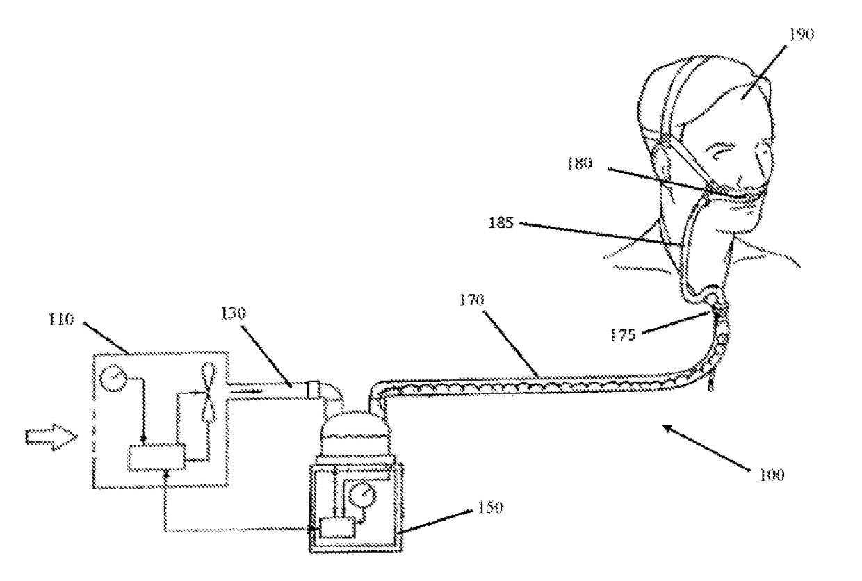
[0046]A respiratory system as herein described can refer to a system that delivers respiratory gases, such as oxygen, carbon dioxide, and / or air to a patient. Any combinations of respiratory gases may also be possible. The patient may be receiving high flow therapy (HFT), treatment for obstructive sleep apnea (OSA), invasive ventilation (INV), or non-invasive ventilation (NIV).

[0047]A respiratory component as herein described can refer to, but is not limited to, a gases source, humidification apparatus, humidification chamber, or medical tube.

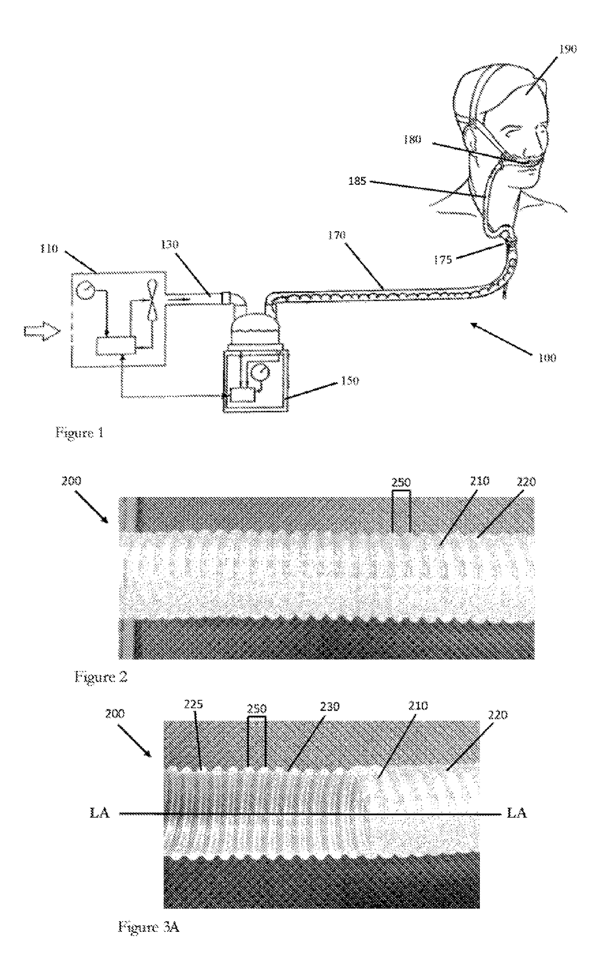
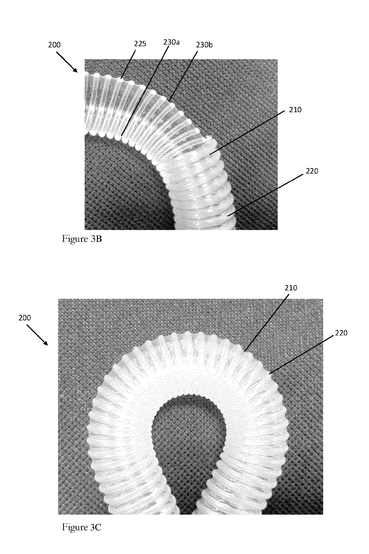
[0048]A medical tube as herein described can refer to a tube, for example, an inspiratory tube, expiratory tube, or interface tube, that connects between a respiratory component and a patient interface.

[0049]A patient interface as herein described can refer to, but is not limited to, a mask, oral mask, nasal mask, nasal cannula, nasal pillows, endotracheal tube, or tracheal mask.

[0050]A gases source as herein described can refer to an apparatus...


PUM


Abstract

A medical tube transports gases to and / or from a patient. The medical tube has an elongate film spirally wrapped with an elongate reinforcing member, which bond to form a lumen. The elongate film has a profile such that the elongate film does not protrude into the lumen of the medical tube upon bending of the medical tube. The elongate reinforcing member can have a D-shaped cross section that can contribute to beneficial characteristics of the medical tube. The elongate reinforcing member can also have a circular cross section.

Description

PRIORITY[0001]This application claims priority to U.S. Patent Application No. 62 / 198,038, filed Jul. 28, 2015, and U.S. Patent Application No. 62 / 054,588, filed Sep. 24, 2014, the entire contents of each of which are incorporated herein by reference.BACKGROUNDTechnical Field[0002]The present disclosure generally relates to tubes configured for use in medical systems. More particularly, the present disclosure relates to tubes configured to attach to patient interfaces in respiratory assistance systems.Description of the Related Art[0003]Medical tubes are used in respiratory systems to convey respiratory gases between a respiratory component, such as a ventilator or a humidifier, and a patient. Respiratory gases can be heated and / or humidified prior to delivery to the patient to mimic the transformation of air that occurs as it enters the respiratory system. Heated medical tubes can deliver the heated and / or humidified respiratory gases directly to a patient interface or, in some case...

Claims


Application Information

Patent Timeline
Patent Type & Authority Applications(United States)
IPC IPC(8): A61M16/08
CPCA61M16/0875A61M2205/0216A61M2205/02A61M2207/00A61M16/1095A61M16/16A61M2205/3368A61M2206/10A61M16/0858
Inventor STOKS, ELMO BENSONMALLINSON, JAYANANDA
Owner FISHER & PAYKEL HEALTHCARE LTD
Why Eureka
Try Eureka