Unlock instant, AI-driven research and patent intelligence for your innovation.

Standing Vehicle Occupant Restraint System

Inactive Publication Date: 2014-08-21
LOCKHEED MARTIN CORP
View PDF1 Cites 4 Cited by
  • Summary
  • Abstract
  • Description
  • Claims
  • Application Information

AI Technical Summary

Benefits of technology

The present invention provides a gunner restraint system and "stroking" system in one simple and inexpensive design. The system prevents service members from being ejected from the vehicle, minimizes leg, spinal, and head injuries, and allows for easy egress and adjustability to every vehicle in the inventory. The design can be used for civilian applications, including commercial vehicles, passenger vehicles, and aircraft.

Problems solved by technology

The issue with this type of operational concept is that vehicles today have been designed to resist penetration from IEDs and land mines without taking into account for these air guards.
The seats in the vehicle are designed to mitigate the energy that is transferred into the vehicle by “stroking” but this system only works for seated passengers and provides no protection to standing service members.
Each person who is standing up in the vehicle is not protected from injuries as a result of mine blast and IED's on the vehicle.
This typically results in severe leg, spinal and head injuries.
On occasion this also results in personnel being injured and then ejected from the vehicle, sometimes causing fatalities.
The US Military is now using gunner restraint systems to prevent service members from being ejected from the vehicle but does not prevent any injuries as a result of energy absorption into the vehicle.
These gunner restraint systems are limited in effective usage and in the event of a vehicle fire they can prevent a service member from escaping the vehicle.
Due to the design of this system it is very hard for a rescue crew to extract a service member during a vehicle fire.
The entire restraint is under the service member and difficult to reach and remove.
In addition the gunner restraint system of the prior art is limited to those who are able to be anchored to the floor of the vehicle.
Rear air guards are not able to be anchored to the floor of the vehicle because they are standing in the path of egress for the dismounted section of the vehicle.
Thus, the current system fails to address 50% of the possible injuries that can be caused as a result of a mine blast or IED event.
It also has a very limited audience / user community because of the anchoring system.

Method used


Image

  • Standing Vehicle Occupant Restraint System
  • Standing Vehicle Occupant Restraint System
  • Standing Vehicle Occupant Restraint System

Examples


Embodiment Construction

[0016]The making and using of the presently preferred embodiments are discussed in detail below. It should be appreciated, however, that the present invention provides many applicable inventive concepts that can be embodied in a wide variety of specific contexts. The specific embodiments discussed are merely illustrative of specific ways to make and use the invention, and do not limit the scope of the invention.

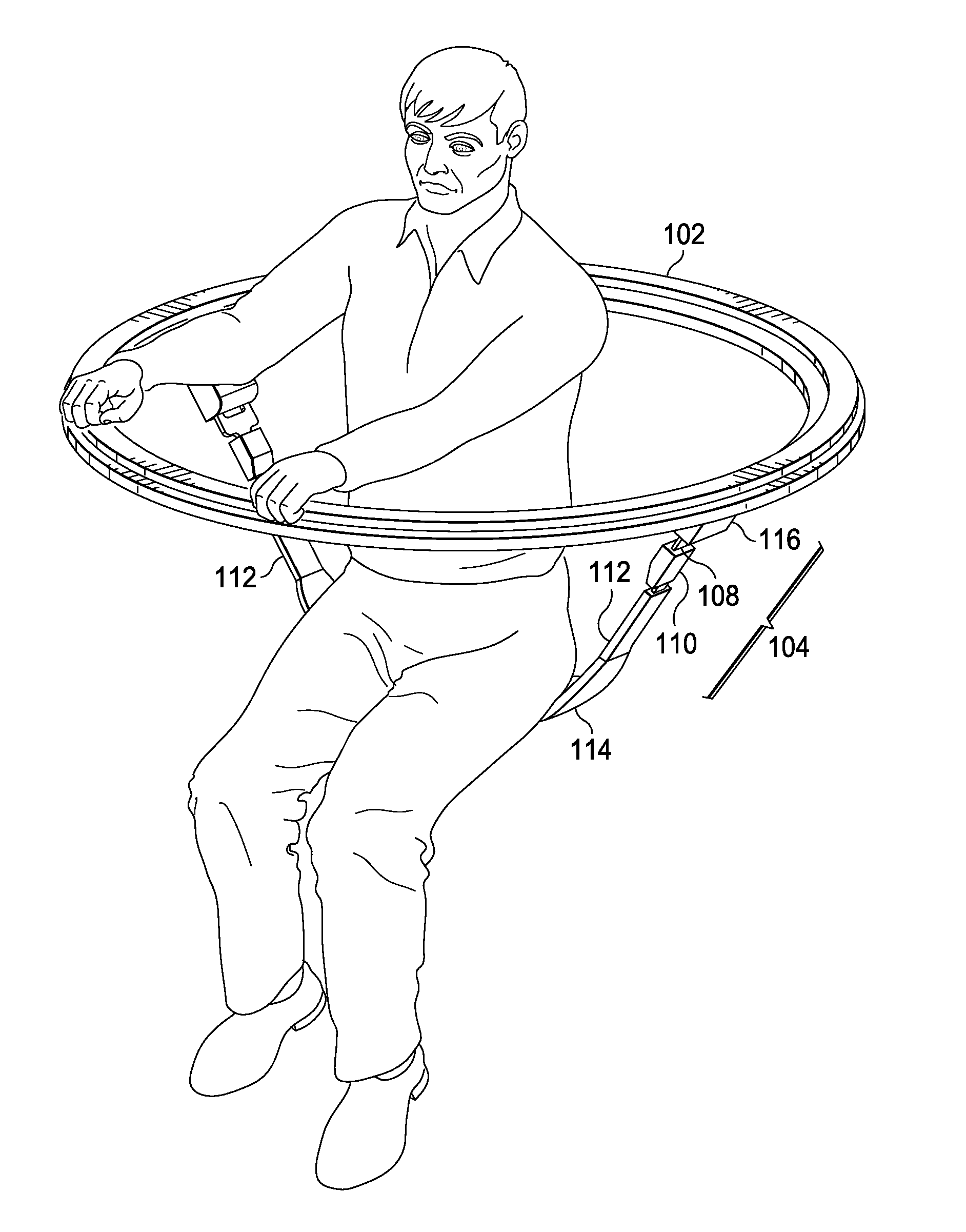
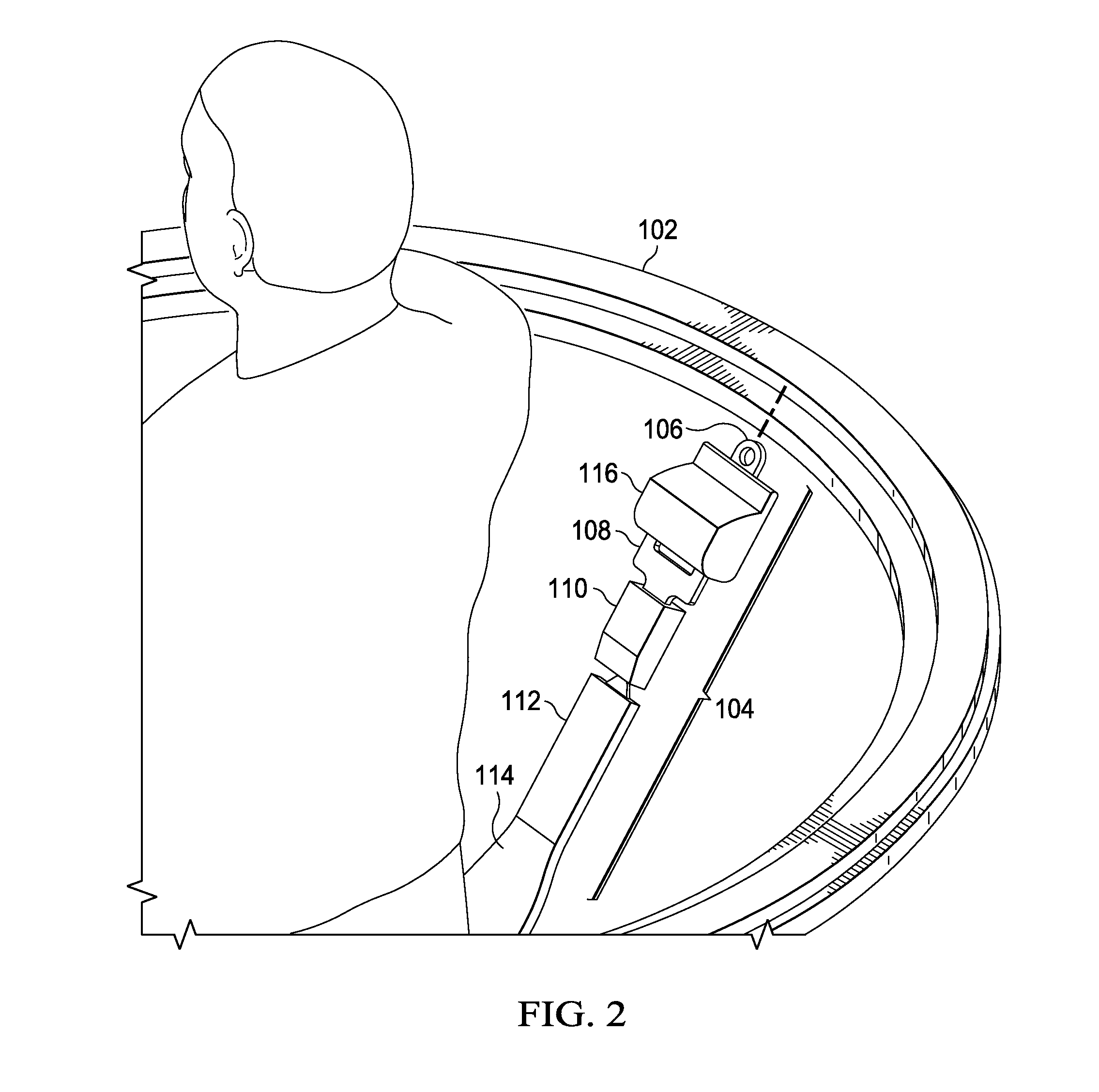
[0017]A system for a standing occupant of a vehicle to mitigate the energy of a blast or abrupt vehicle motion may have a seat to support the occupant that is attached to the vehicle with an energy absorbing mechanism. A harness is worn by an occupant, and an energy absorbing strap system attaches the harness and user to the vehicle. For example, the restraint system may be a rock climbing harness with an energy absorption seat sewn into it. In other examples, a belt, sling, or the like maybe used to secure the occupant. An energy absorbing mechanism is disposed between the o...


PUM


Abstract

Presented herein is a restraint system comprising an attachment point configured to attach to a hatch opening of a vehicle, a harness having a seat and a strap attached to the attachment point and to the seat. The harness is configured to accept an occupant and support a portion of the occupant at a position below the hatch opening. The restraint system further comprises an energy absorption mechanism configured to dampen rapid acceleration or deceleration of the occupant. The strap is attached to the attachment point by a quick release mechanism. The energy absorption mechanism may comprise a retraction mechanism having a damper mechanism that is a spring, a coil spring, a viscous fluid, a fluid having a dynamically changeable viscosity or a magnetorheological fluid. The energy absorption mechanism may comprise tear-away sections configured to dampen vehicle motion energy.

Description

RELATED APPLICATIONS[0001]This application claims the benefit of U.S. Provisional Patent Application Ser. No. 61 / 619,117, filed on Apr. 2, 2012, and entitled “Standing Vehicle Occupant Restraint System,” which is incorporated herein by reference.TECHNICAL FIELD[0002]The present invention relates generally to a system and method for restraining an occupant of a vehicle.BACKGROUND[0003]Today, modern combat forces operating in high threat areas have been forced to operate their combat vehicles with open hatches for roof air guards to protect the vehicles. These air guards are operating while standing in the vehicles and are exposed from the waist / mid chest above the roof of the vehicle through air guard hatches (small doors in the roof of the vehicles). They operate with both personal and crew served weapons to protect the vehicle from roof top threats and they observe the areas surrounding the vehicle to prevent up close attacks. These members of the team also assist the driver in loc...

Claims


Application Information

Patent Timeline
IPC IPC(8): B60R22/24B60R22/36B60R22/28
CPCB60R22/24B60R22/28B60R2022/283B60R2022/281B60R2022/282B60R22/36A62B35/0012A62B35/04B60N2/4242B60N2002/247
Inventor SHEPHERD, PATRICK E.VILLARREAL, RICARDO
Owner LOCKHEED MARTIN CORP
Features
  • R&D
  • Intellectual Property
  • Life Sciences
  • Materials
  • Tech Scout
  • Unparalleled Data Quality
  • Higher Quality Content
  • 60% Fewer Hallucinations
Learn More