

Mirror unit and image acquisition unit
a technology which is applied in the field of mirror unit and image acquisition unit, can solve the problems of not being able to provide a free-curved surface suitable for the surface shape of the specimen, and being difficult to focus on the entire surface of an undulate specimen
- Summary
- Abstract
- Description
- Claims
- Application Information
AI Technical Summary
Benefits of technology
Problems solved by technology
Method used
Image

Examples
first embodiment
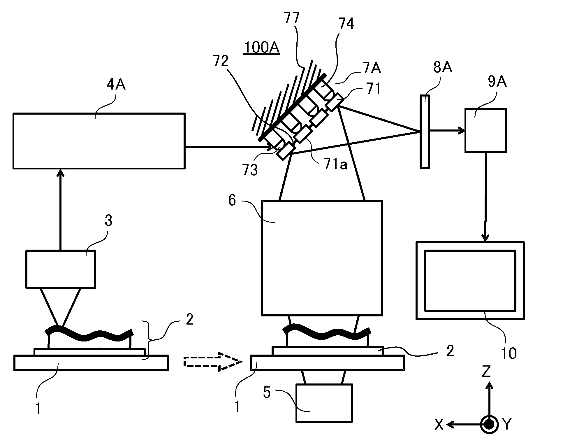
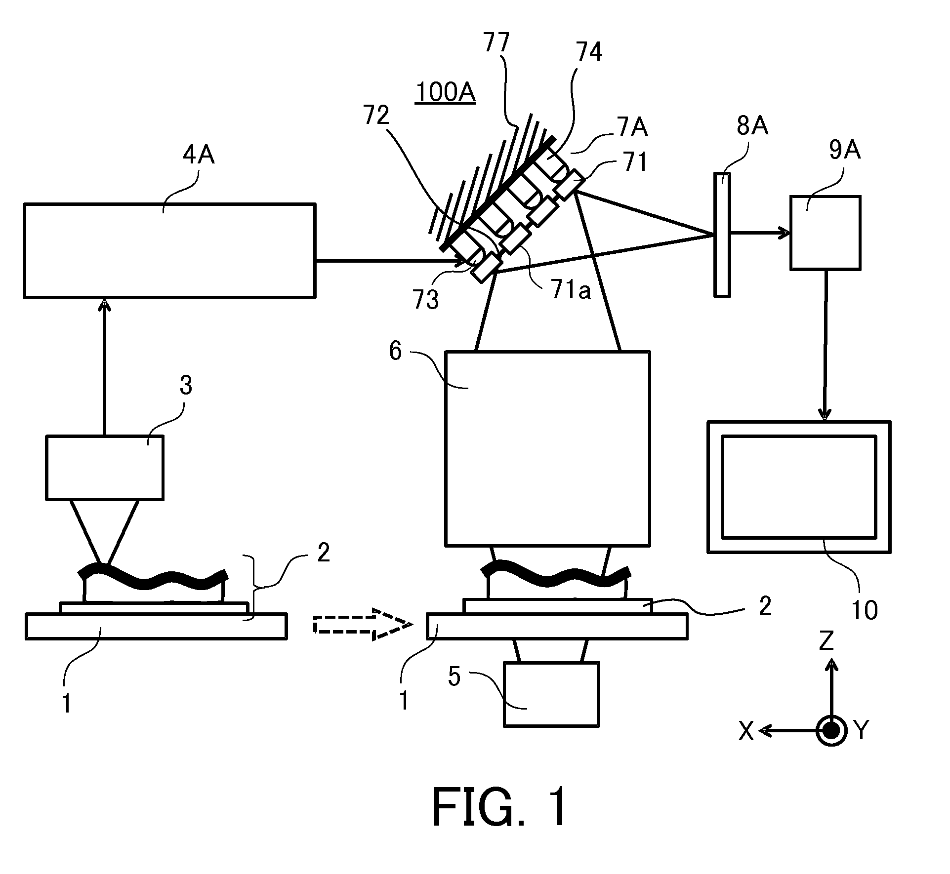
[0022]FIG. 1 is a schematic view of principal part of an image acquisition unit 100A according to the first embodiment. The image acquisition unit 100A includes a measurement section and a digital microscope body (an image acquisition unit body). The image acquisition unit of this embodiment is, but not limited to, a digital microscope. The measurement section and the digital microscope body may constitute a single apparatus or separate apparatuses.
[0023]First, an object 2 is held on a stage 1 in the measurement section. The object 2, such as a pathological specimen (a sample), is placed on a slide glass and sandwiched by the slide glass and a transparent protector (a cover glass). In FIG. 1, an X-Y plane is a plane perpendicular to a Z axis that is an optical axis of an objective optical system 6, which will be described later. The stage 1 is configured movably in X-, Y-, and Z-axis directions and around each axis.
[0024]A measurement unit 3 (a first measurement unit) measures a dep...
second embodiment
[0062]FIG. 8A is a schematic view of principal part of an image acquisition unit 100B according to a second embodiment. Those elements, which are the corresponding elements illustrated in FIG. 1, are designated by the same reference numerals. While the image acquisition unit 100B includes a control system, it is different from the image acquisition unit 100A in that it includes a controller 4B instead of the controller 4A and a deformable mirror unit instead of the deformable mirror unit 7A.
[0063]As the driver 74 displaces with the corresponding connector 73, the segment mirror 71 or the flexible member 72 changes a position or an orientation and the deformable mirror unit 7B has a reflection surface shape corresponding to the surface shape of the object 2 similar to the first embodiment. In this embodiment, a driving amount of the driver 74 is equal to a moving amount (a displacement amount) of the driver 74. Similarly, the controller 4B calculates the moving amount of the driver 7...
third embodiment
[0068]FIG. 9A is a schematic view of principal part of an image acquisition unit 100C according to a third embodiment. Those elements, which are the corresponding elements illustrated in FIG. 1, are designated by the same reference numerals. The image acquisition unit 100C is different from the image acquisition unit 100B in that it includes a controller 4C instead of the controller 4A and a deformable mirror unit 7C instead of the deformable mirror unit 7A.
[0069]As the driver 74 displaces with the corresponding connector 73, the segment mirror 71 or the flexible member 72 changes a position or an orientation and the deformable mirror unit 7C has a reflection surface shape corresponding to the surface shape of the object 2, similar to the first embodiment. In this embodiment, a driving amount of the driver 74 is a driving amount which the driver 74 gives to the segment mirror 71 or the flexible members 72. Similarly, the controller 4C calculates the moving amount of the driver 74 ba...
PUM
 Abstract
Description
Claims
Application Information