
Multi-Beam ROS Imaging System

Inactive Publication Date: 2014-08-21
XEROX CORP
View PDF5 Cites 0 Cited by
  • Summary
  • Abstract
  • Description
  • Claims
  • Application Information

AI Technical Summary

Benefits of technology

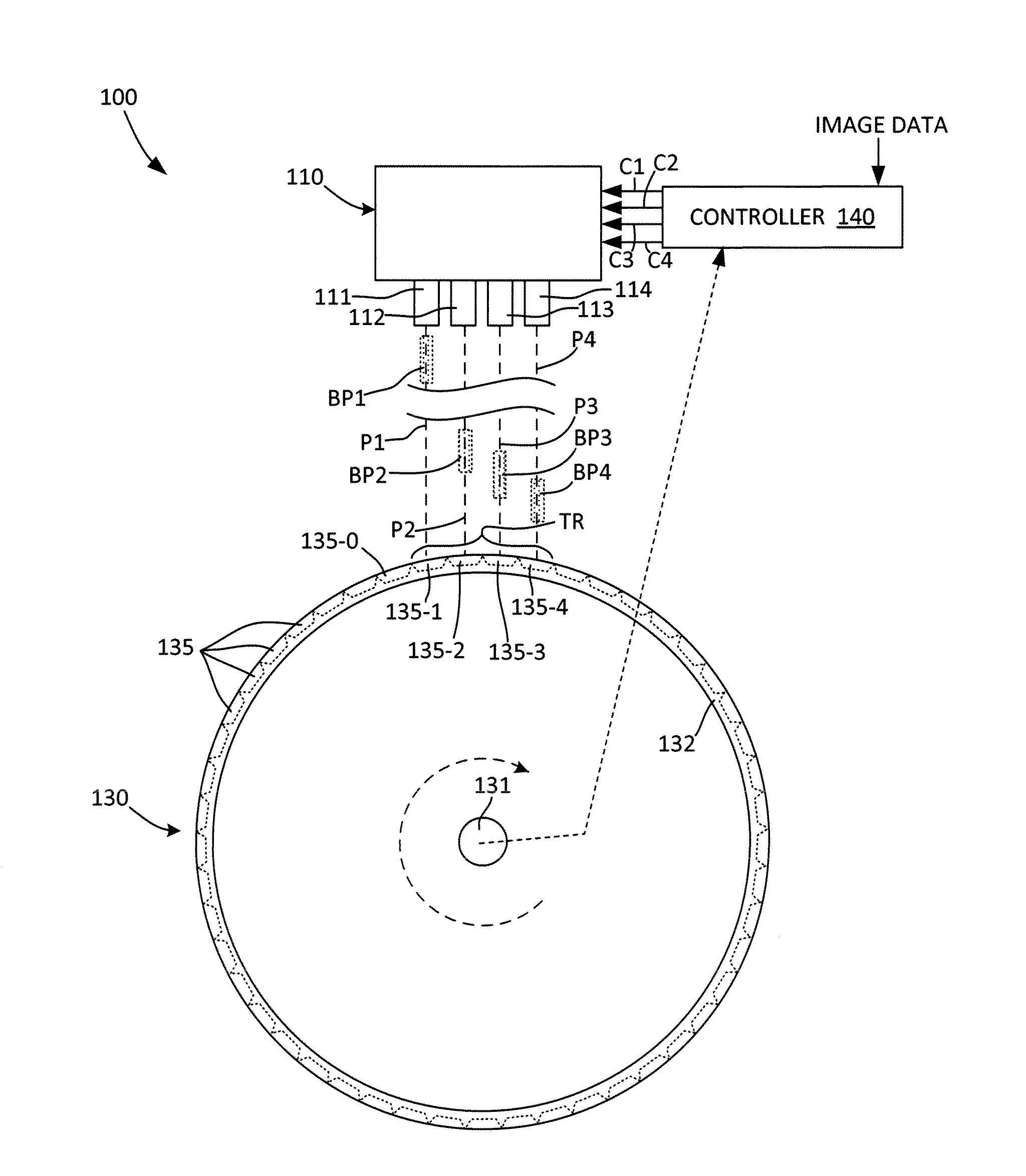
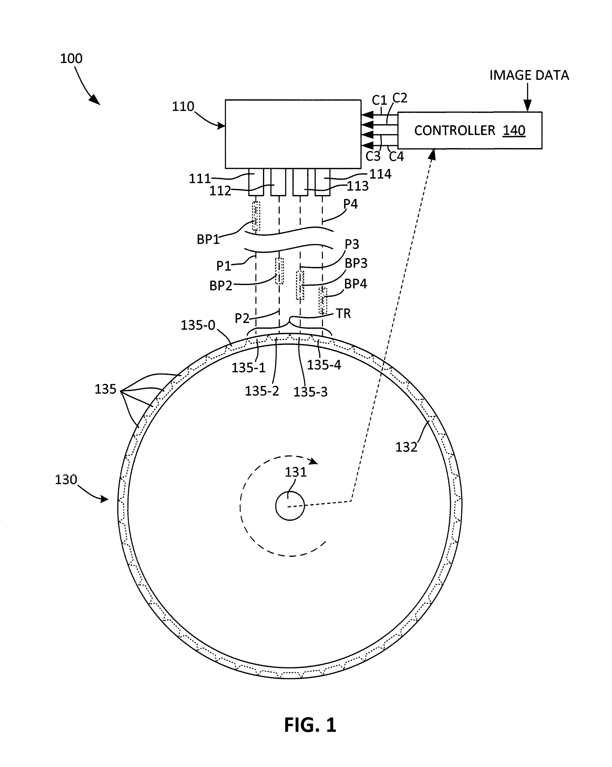
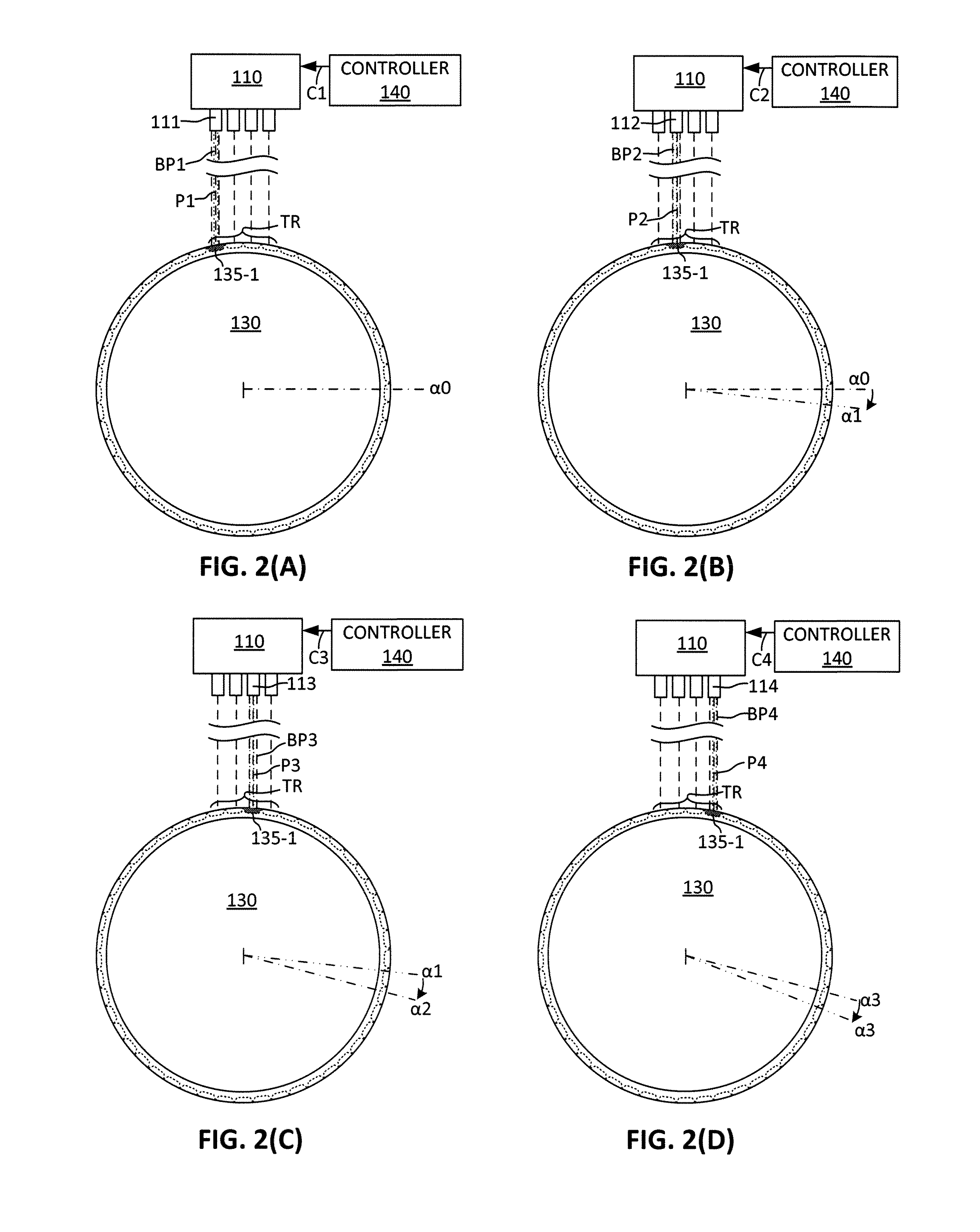
[0006]The present invention is directed to a multiple-beam imager including an array of light sources (e.g., laser diodes) that are arranged to transmit light beam pulses (energy doses) along parallel paths onto a targeted group of print plate spots (i.e., unit regions of an imaging cylinder print plate that are disposed in a circumferential target region during a given imaging period). The light sources are controlled to generate the light beam pulses in coordination with rotation of the imaging cylinder such that, as each print plate spot is rotated through the target region, it is sequentially positioned during successive imaging periods to receive light beam pulses from each of the sequentially-aligned light sources. For example, during an initial imaging period, when a selected print plate spot is aligned with a first beam path, a first light source is actuated to transmit a first beam pulse along the first beam path onto the selected print spot, thereby transferring a first energy dose to the selected print plate spot. During a subsequent imaging period, when the selected print plate spot is aligned with an adjacent se

Problems solved by technology

A problem with the conventional imaging single-beam ROS imaging system described above is that, in order to deliver sufficient energy to the print plate within the very short dwell time of the raster beam (i.e., to achieve high page-per-minute printer speeds, a very high energy laser source (e.g., on the order of a KiloWatt or more) is required.
That is, a limiting characteristic of the conventional

Method used


Image

  • Multi-Beam ROS Imaging System
  • Multi-Beam ROS Imaging System
  • Multi-Beam ROS Imaging System

Examples


Example

DETAILED DESCRIPTION OF THE DRAWINGS

[0017]The present invention relates to an improvement in imaging systems that are utilized, for example, in printing systems. The following description is presented to enable one of ordinary skill in the art to make and use the invention as provided in the context of a particular application and its requirements. As used herein, directional terms such as “upper”, “upwards”, “lower”, “downward”, “front”, “rear”, are intended to provide relative positions for purposes of description, and are not intended to designate an absolute frame of reference. Various modifications to the preferred embodiment will be apparent to those with skill in the art, and the general principles defined herein may be applied to other embodiments. Therefore, the present invention is not intended to be limited to the particular embodiments shown and described, but is to be accorded the widest scope consistent with the principles and novel features herein disclosed.

[0018]FIG....


PUM


Abstract

A multiple-beam imager includes multiple light sources (e.g., laser diodes) that transmit light beam pulses (energy doses) along parallel paths onto print plate spots disposed in a circumferential target region during each imaging period. The beam pulses are coordinated with rotation of the imaging cylinder such that, as a selected print plate spot is rotated through the target region, it is sequentially positioned during successive imaging periods to receive light beam pulses from each of the sequentially-aligned light sources, whereby the selected print plate spot receives multiple energy doses (e.g., one during each raster-scan) as it passes through the target region, thereby gradually heating and then evaporating the fountain solution predisposed over the selected print spot. A polygon mirror is used to raster-scan the beam pulses along parallel raster-scan zones.

Description

FIELD OF THE INVENTION[0001]This invention relates to imaging systems, and more particularly to raster-output-scanner imaging systems utilized, for example, in printing systems.BACKGROUND OF THE INVENTION[0002]FIG. 8 is a simplified cross-sectional view showing a generalized conventional printing system that utilizes an imaging system including an imaging cylinder having a cylindrical print plate. The print plate is dampened with a uniform thin film of fountain solution (FS). Next, a high power modulated light source is used to selectively vaporize the FS where image content is destined. Not shown but known to be critical is a suction manifold in close proximity to the imaging zone to remove the FS vapor cloud that forms before it can interfere with the imaging process. Next, the plate passes through an inker nip, and the exposed portions of the plate are coated with ink. If needed, an ultraviolet (UV) lamp is used to partially cure the ink on the print plate in order to enhance its...

Claims


Application Information

Patent Timeline
IPC IPC(8): G02B26/10
CPCG02B26/101G02B26/123
Inventor MOORE, STEVEN R.
Owner XEROX CORP
Learn More