
Drive system for ground spoiler, and aircraft

a technology for driving systems and aircraft, applied in the direction of automatic actuation, air braking surfaces, transportation and packaging, etc., can solve the problems of ground spoiler creating a stall behind ground spoiler, wheel rotation not being properly adjusted, and locking

Active Publication Date: 2014-08-28
MITSUBISHI AIRCRAFT
View PDF10 Cites 16 Cited by
  • Summary
  • Abstract
  • Description
  • Claims
  • Application Information

AI Technical Summary

Benefits of technology

The present invention is a drive system for a ground spoiler which produces a reliable effect. It is able to automatically deploy the ground spoiler when the wheel is locked, ensuring safety and efficiency during operation. Additionally, it can be selectively deployed based on air speed and can even close automatically when the wheel is locked. The invention uses air speed as a reference speed to determine when to deploy the ground spoiler, ensuring safe and automatic operation.

Problems solved by technology

When the ground spoiler is deployed after the aircraft lands on the ground, the ground spoiler creates a stall behind the ground spoiler.
However, if a runaway surface is wet or frozen and thus slippery, the wheel cannot rotate properly and may thus become locked.

Method used


Image

  • Drive system for ground spoiler, and aircraft
  • Drive system for ground spoiler, and aircraft
  • Drive system for ground spoiler, and aircraft

Examples


Embodiment Construction

[0030]In the following, the present invention is described in detail based on an embodiment shown in the accompanying drawings.

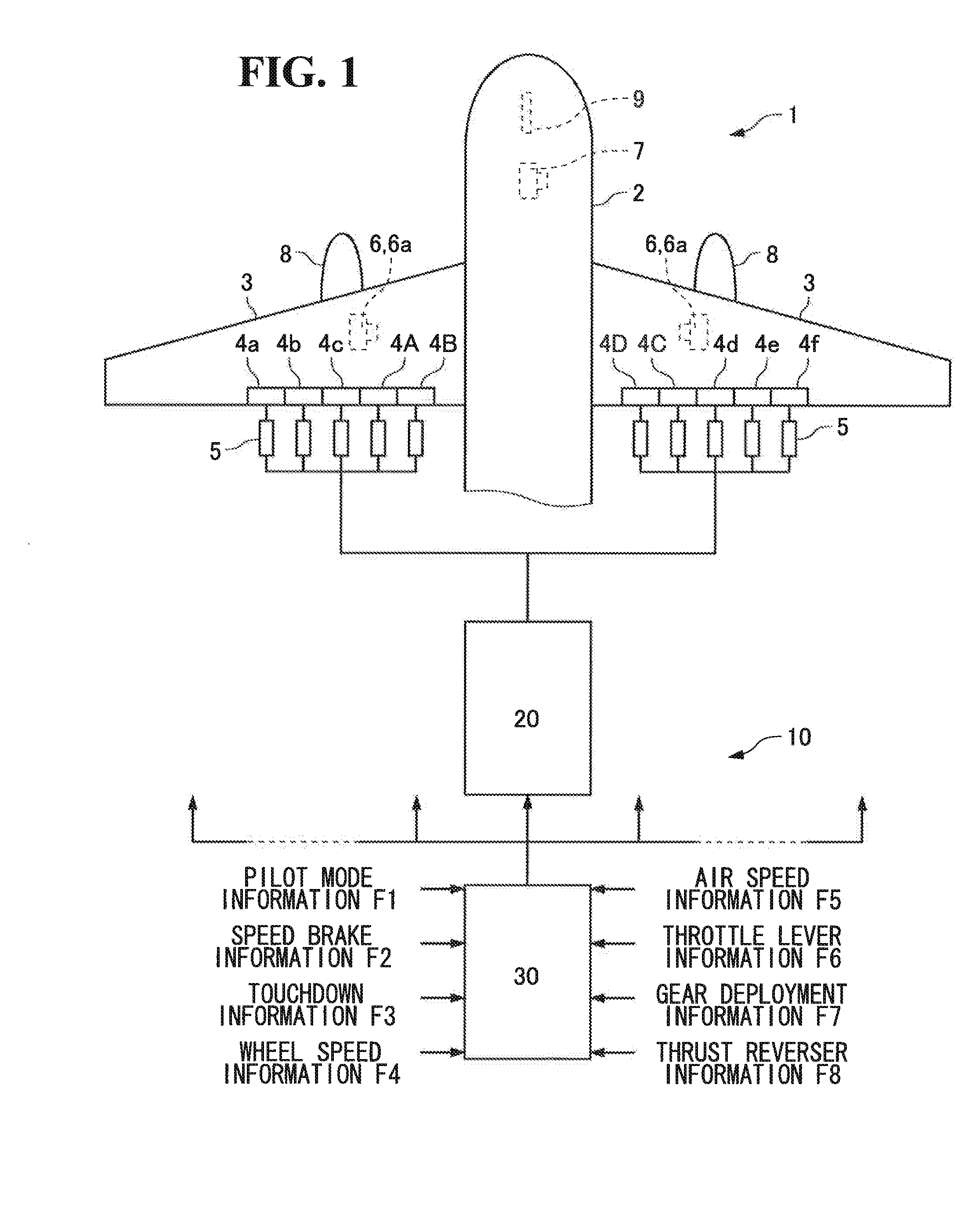
[0031]As shown in FIG. 1, a ground spoiler drive system 10 according to the present embodiment automatically deploys (sometimes referred to as “automatic deployment” below) ground spoilers 4A to 4D that are provided at trailing edges of main wings 3 of an aircraft 1 without being operated by a pilot, and also automatically closes (sometimes referred to as “automatic closing” below) the ground spoilers 4A to 4D after deploying the ground spoilers without being operated by a pilot.

[0032]The aircraft 1 includes main gears 6 provided on lower surfaces of the main wings 3, and a nose gear 7 provided on a lower surface of a fuselage 2 ahead of the main gears 6 in a flight direction.

[0033]Each of the ground spoilers (sometimes abbreviated to “GS” below) 4A, 4B, 4C, and 4D is coupled to an actuator 5 that is driven by a hydraulic source. When the respective actuator...


PUM


Abstract

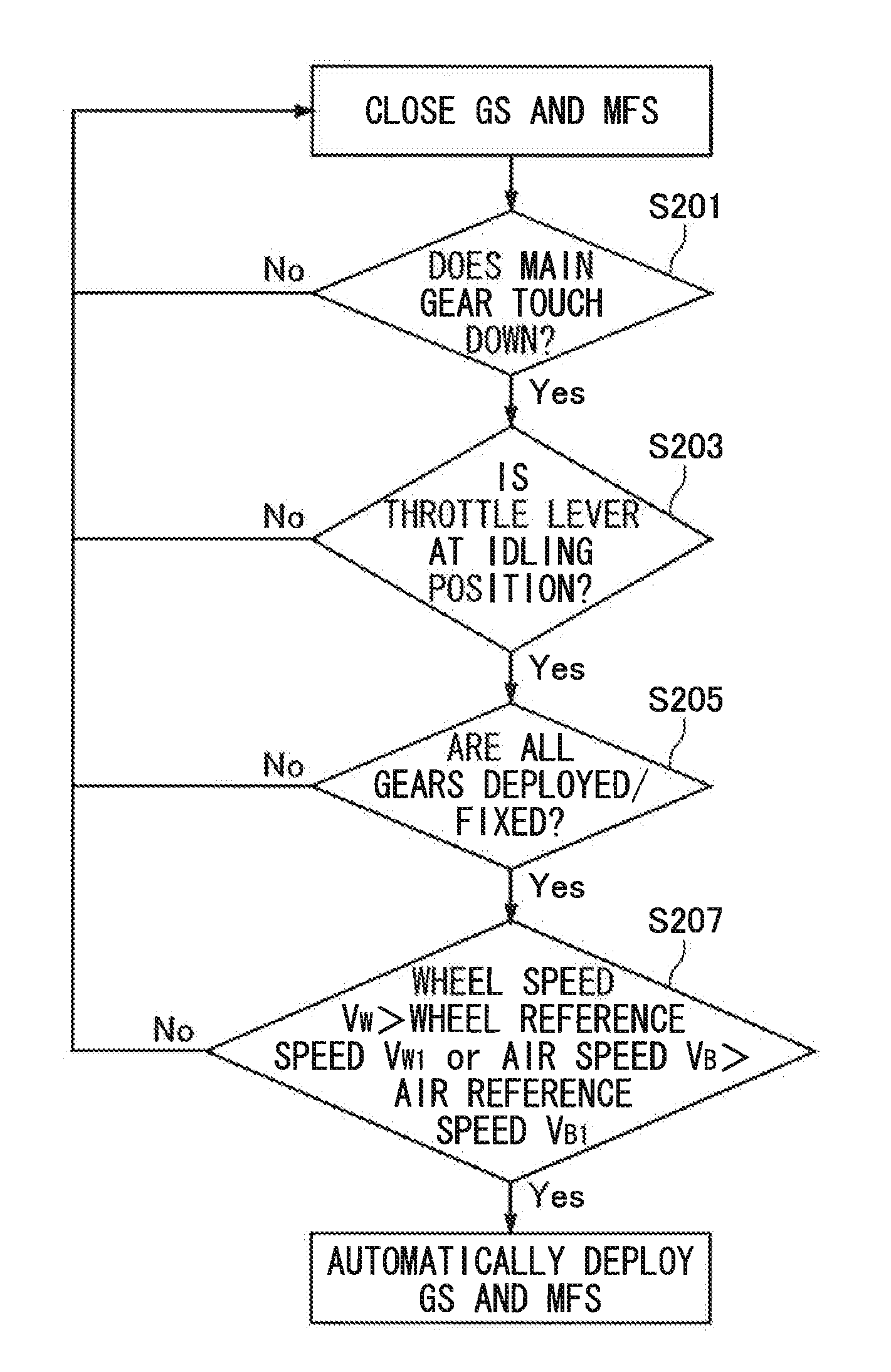
The present invention provides a drive system which can automatically deploy a ground spoiler even when a wheel is locked. A drive system for a ground spoiler deploys closed ground spoilers 4A to 4D when a wheel speed VW exceeds a wheel reference speed VW1 or when an air speed VB exceeds an air reference speed VB1 after a main gear 6 touches down. The system may also close the deployed ground spoilers 4A to 4D when the wheel speed VW is smaller than a wheel reference speed VW2 or when the air speed VB is smaller than an air reference speed VB2.

Description

BACKGROUND OF THE INVENTION[0001]1. Field of the Invention[0002]The present invention relates to a technique for automatically deploying a ground spoiler that is provided at a main wing of an aircraft.[0003]2. Description of the Related Art[0004]Spoilers provided at a main wing of an aircraft are provided in order to reduce a lift generated by the main wing. The spoilers are generally divided into a flight spoiler that operates during a flight, a ground spoiler that operates in a running state at the time of takeoff and landing, and a multi-function spoiler that operates both during a flight and in a running state. In the present invention, the ground spoiler is used as a concept including the multi-function spoiler that operates in a running state as well.[0005]The ground spoiler is a flight control surface mounted to a main wing, and is one of devices for reducing a lift of an aircraft. When the ground spoiler is deployed after the aircraft lands on the ground, the ground spoiler ...

Claims


Application Information

Patent Timeline
Patent Type & Authority Applications(United States)
IPC IPC(8): B64C13/16B64C13/24
CPCB64C13/16B64C13/24B64C9/32
Inventor HARA, AKIHIRO
Owner MITSUBISHI AIRCRAFT
Learn More