
Leaf spring and compressor with leaf spring

a leaf spring and compressor technology, applied in the field of leaf springs and compressors, can solve the problems of inability to replace the flat springs used in linear compressors, inability to ensure the radial rigidity, and likely oscillatory movement relative to the flexible disks of most leaf springs

Inactive Publication Date: 2014-08-28
WHIRPOOL SA
View PDF97 Cites 20 Cited by
  • Summary
  • Abstract
  • Description
  • Claims
  • Application Information

AI Technical Summary

Benefits of technology

The present invention provides leaf springs that can securely position the resonant oscillatory assembly of a linear compressor in relation to its shell or intermediate body. This helps to ensure the stability and efficiency of the compressor.

Problems solved by technology

In this case, said spacers have only the function of attenuating vibration between flexible disks, and therefore, they are likely to present oscillatory movements relative to the flexible disks.
The current state of the art also comprises different types of flat leaf springs; however (and as well as the two examples recited above), most of those types of leaf springs is not able to replace the flat springs used in linear compressors.
Such exemplifications of leaf springs are unable to ensure the radial rigidity that is necessary for the correct functioning of the resonant oscillatory assembly, that is, they are unable to ensure the radial positioning between resonant oscillating assembly and an intermediate body (or shell) of a linear compressor.
Thus, those settings allow the flat springs, when in a state of maximum compression, to be capable of blocking (condition where the “links” of a spring (or a leaf springs) are physically contacted to each other, substantially changing the resilient characteristics of the assembly), this characteristic being highly undesirable in applications related to oscillatory movements, such as the linear compressors.
Therefore, the current state of the art does not provide leaf springs that may be used in linear compressors, in particular, in linear compressors based on resonant oscillatory mechanisms.

Method used


Image

  • Leaf spring and compressor with leaf spring
  • Leaf spring and compressor with leaf spring
  • Leaf spring and compressor with leaf spring

Examples


Embodiment Construction

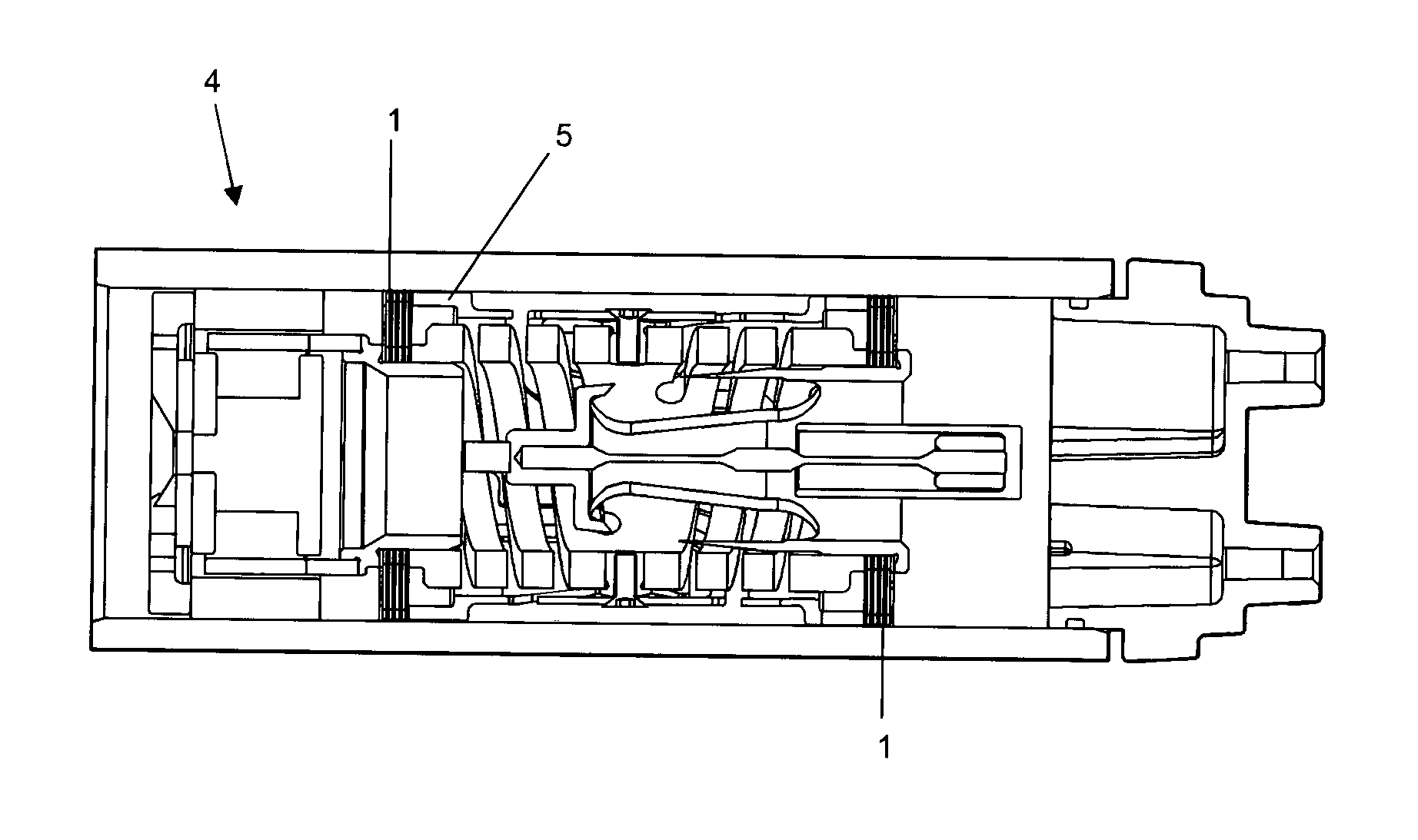
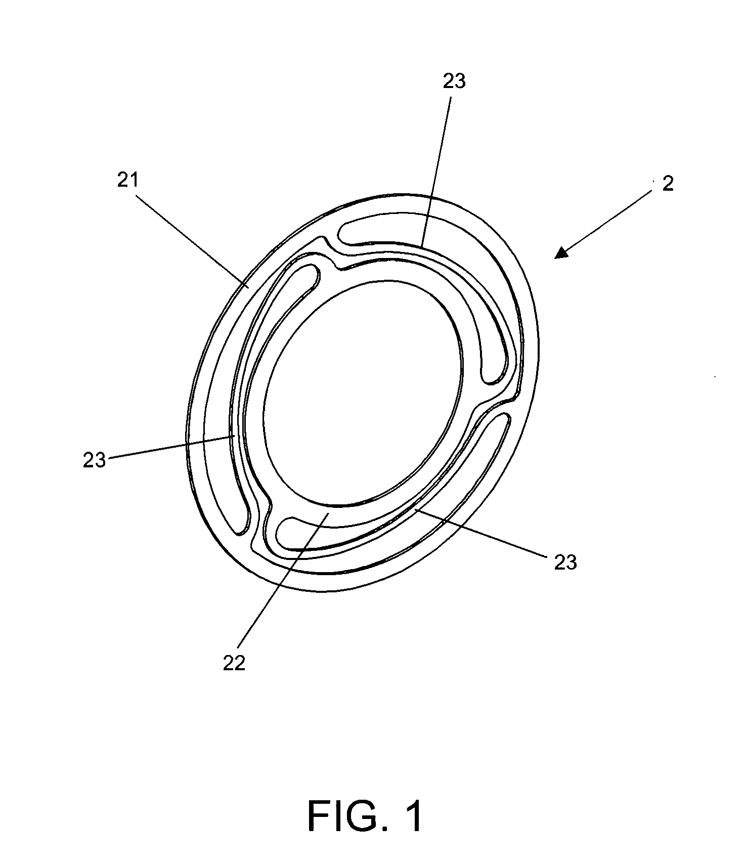
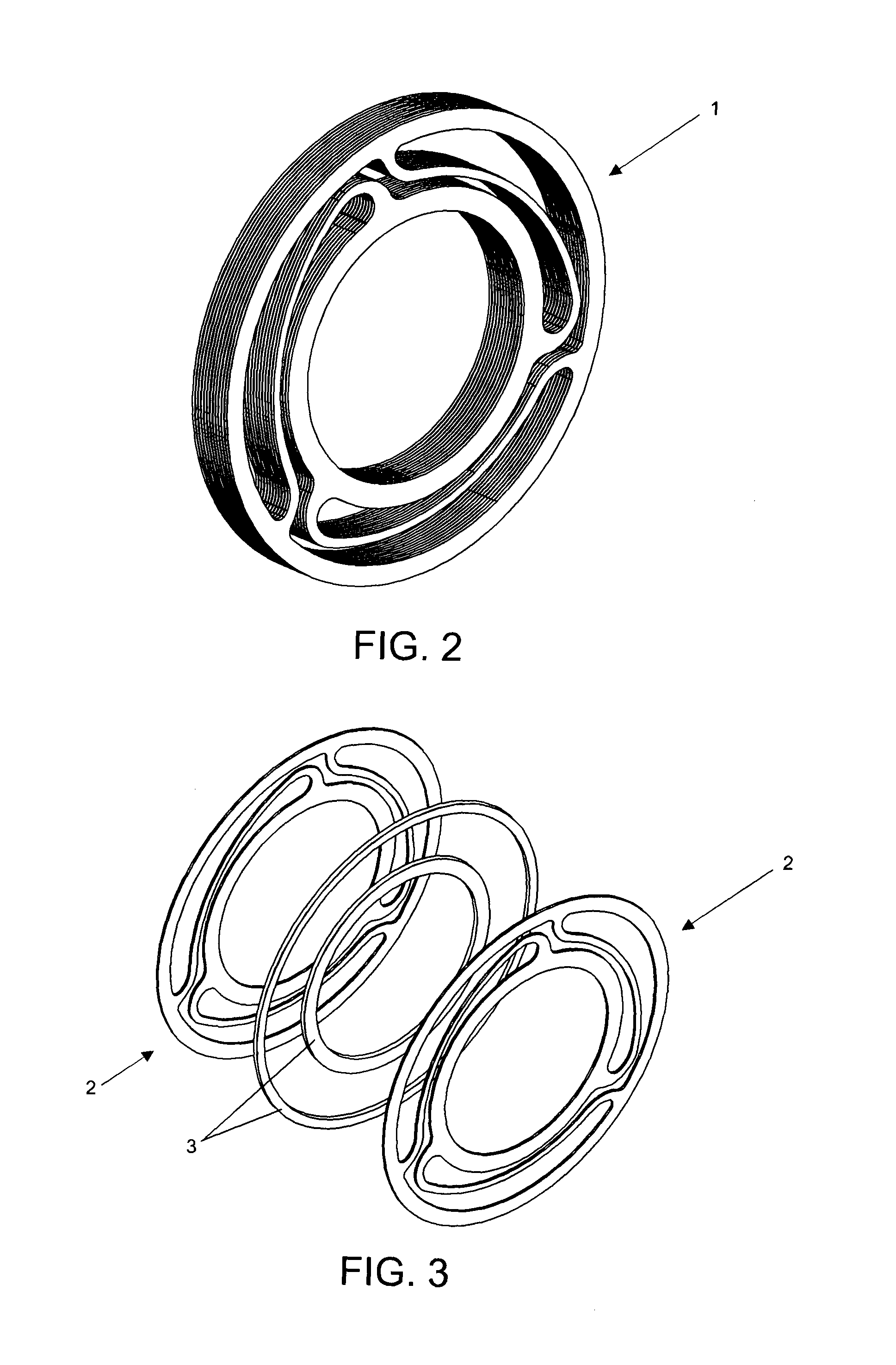
[0031]According to the concepts and objects of the present invention, the present invention discloses a leaf springs 1 capable of incorporating a compressor—based on a resonant oscillating mechanism—mainly comprised of flat springs adjacently arranged and spaced from each other by spacers, each pair of flat spring providing a spacer between at least two springs that integrate the pair.

[0032]Also according to the present invention, each of the flat springs defines two supporting regions and an axially resilient region, only the supporting regions of the flat springs being “interconnected” to each other. Thus, axially resilient regions of a flat spring (when the same are associated with each other, conforming the leaf springs itself) will not exhibit any type of physical contact with axially resilient regions of other flat springs adjacently disposed.

[0033]This concept avoids that, at full load deformation, the leaf springs is subject to blocking, since the axially resilient regions a...


PUM


Abstract

The present invention relates to compressor leaf springs, in particular, linear compressor leaf springs; the leaf springs comprising at least one spacer (3) disposed between at least a pair of flat springs (2), each flat spring (2) being comprised by at least one outer ring (21), at least one inner ring (22) and at least one connection extension (23) which connects an outer rim (21) to an inner ring (22); According to the present invention, it is defined at least one section of physical contact between at least a pair of outer rims (21) defined by at least one spacer (3), at least one section of physical contact between at least a pair of inner rims (22) defined by at least one spacer (3), and at least one free section of physical contact between at least two connection extensions (23) adjacently arranged.

Description

FIELD OF THE INVENTION[0001]The present invention relates to compressor leaf springs, in particular, linear compressor leaf springs, and a compressor provided with leaf springs, in particular, a linear compressor that is provided with at least two leaf springs cooperatively disposed at least one of the linear compressor mechanisms.BACKGROUND OF THE INVENTION[0002]As it is well known to those skilled in the art, a compressor comprises a mechanical (or electromechanical) device capable of raising the pressure of a particular working fluid, so that said working fluid, once “pressurized”, can be used in different applications.[0003]Among the types of compressor belonging to the current state of the art, it is known the reciprocating compressors. Such compressors are capable of raising the pressure of a working fluid by changing volume of a “chamber” where the mentioned working fluid is temporarily disposed. In this sense, reciprocating compressors uses a cylinder-piston assembly for pro...

Claims


Application Information

Patent Timeline
IPC IPC(8): F04B9/06F16F1/32
CPCF04B9/06F16F1/32F04B35/045F04B39/1073F16F1/326
Inventor ROMAN, ALISSON LUIZTAKEMORI, CELSO KENZOVOLLRATH, INGWALDCOUTO, PAULO ROGERIO CARRARA
Owner WHIRPOOL SA
Learn More