
Chest compressor

a compressor and chest technology, applied in the field of chest compressors, can solve the problems of inability to remove cellular waste products, sudden decrease in oxygen delivery to cells, large system-wide harm to vital organs, etc., and achieve the effect of stimulating circulation and light weigh

Inactive Publication Date: 2006-06-13
SUNLIFE SCI INC
View PDF16 Cites 48 Cited by
  • Summary
  • Abstract
  • Description
  • Claims
  • Application Information

AI Technical Summary

Benefits of technology

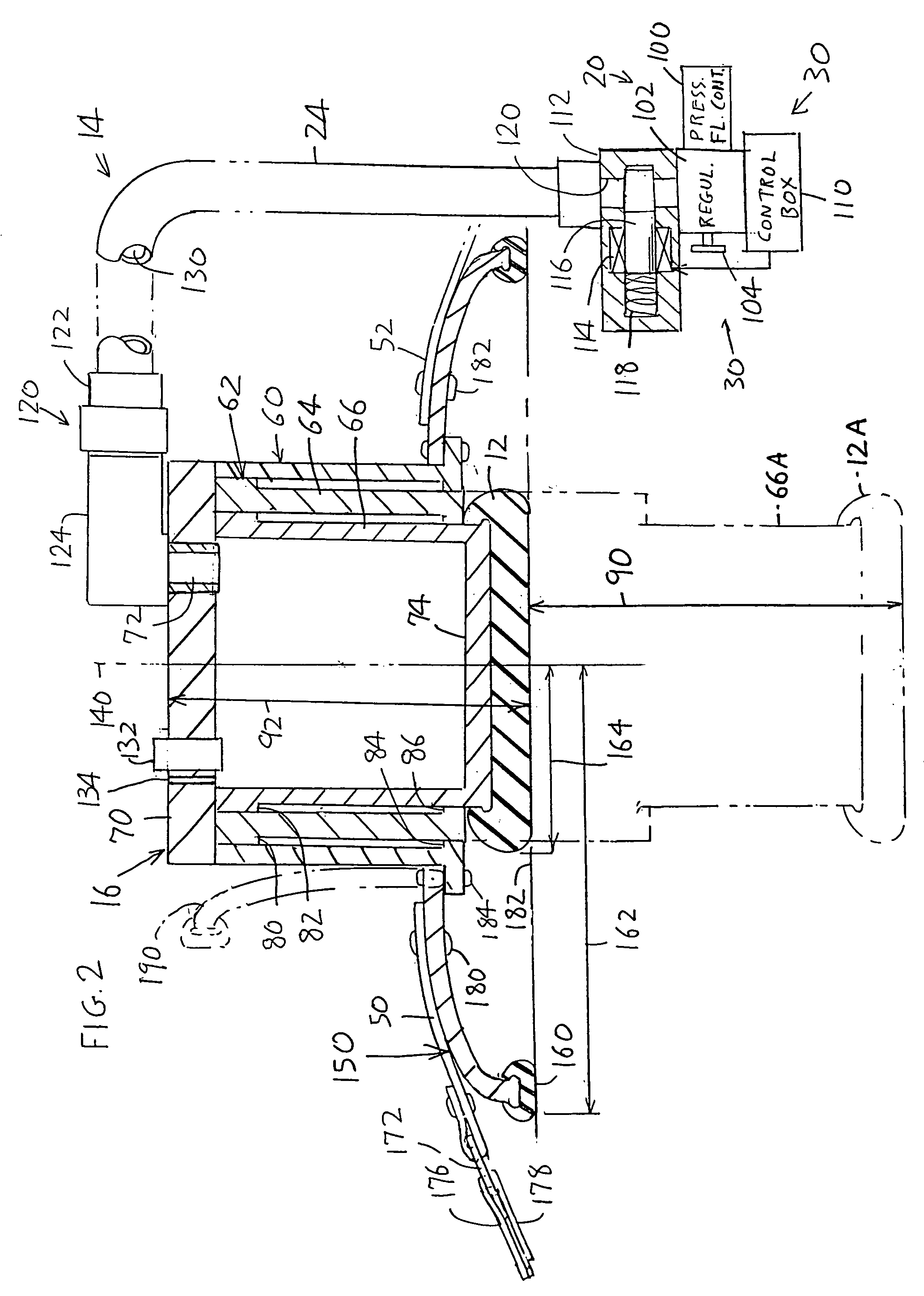
[0004]In accordance with one embodiment of the present invention, an apparatus is provided for applying compressions to the chest of a patient to stimulate circulation, which is compact, of light weight, and reliable. The apparatus includes an energizable compressor assembly with a pressing member that can apply a series of pulses to the chest of the patient, and a torso wrap that wraps around the back of the patient's torso so the patient's torso is sandwiched between the compressor and the back portion of the torso wrap. The compressor assembly includes an actuator that is energized by pressured fluid such as pressured gas and that is coupled to the torso wrap. The compressor assembly also includes a fluid source and control that are coupled through an elongated flexible tube to the actuator so the pressure source and control can lie on the ground beside the patient. The control includes a valve that briefly opens periodically to send pulses of air to the actuator to cause the pressing member to be depressed in pulses.

Problems solved by technology

Low systemic profusion is caused by several forms of circulatory shock, including hemorrhage, sepsis, and cardiac arrest, all of which cause large system-wide harm to vital organs.
A first mode of damage results from the sudden decrease in oxygen delivery to cells, while a second mode of damage results from the inability to remove cellular waste products such as CO2.

Method used


Image

  • Chest compressor
  • Chest compressor
  • Chest compressor

Examples


Embodiment Construction

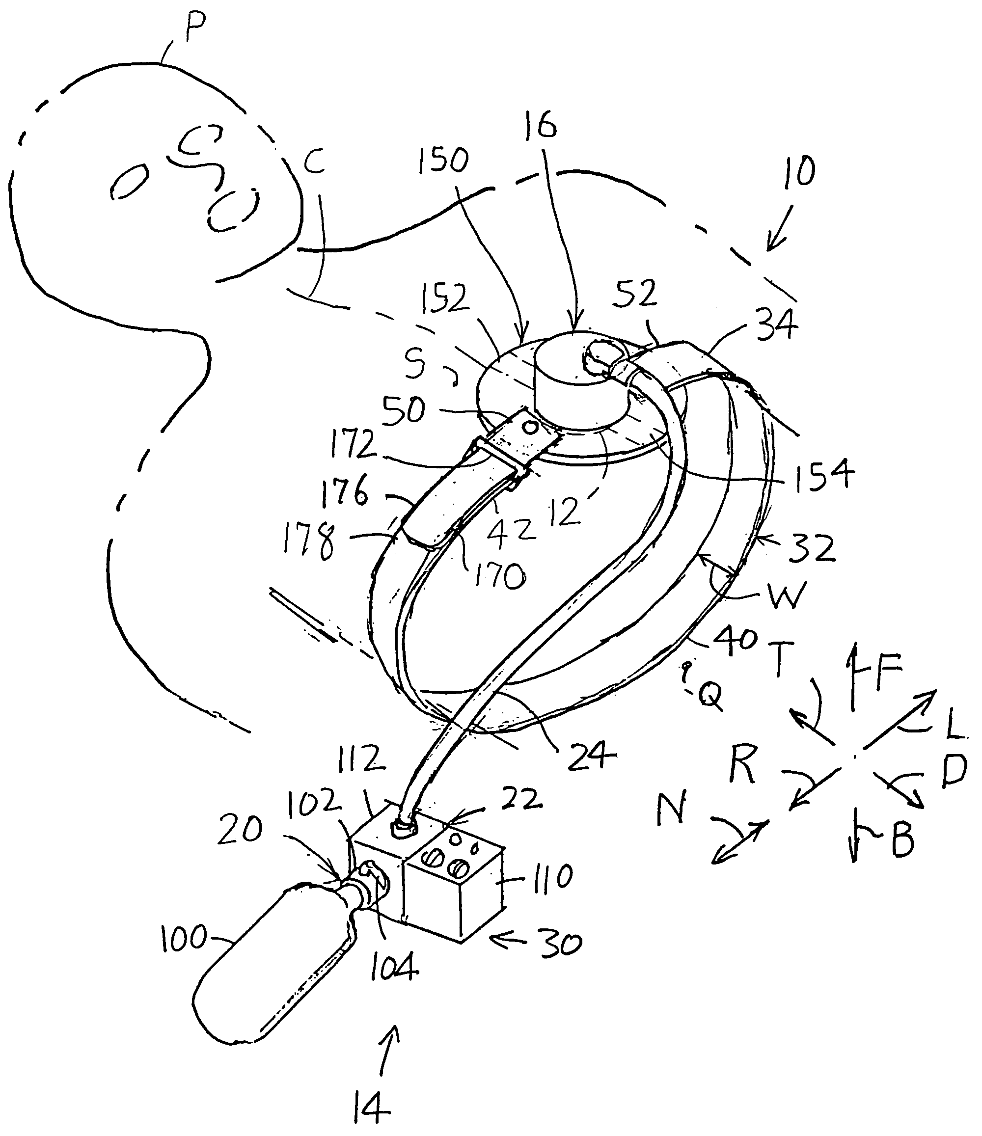
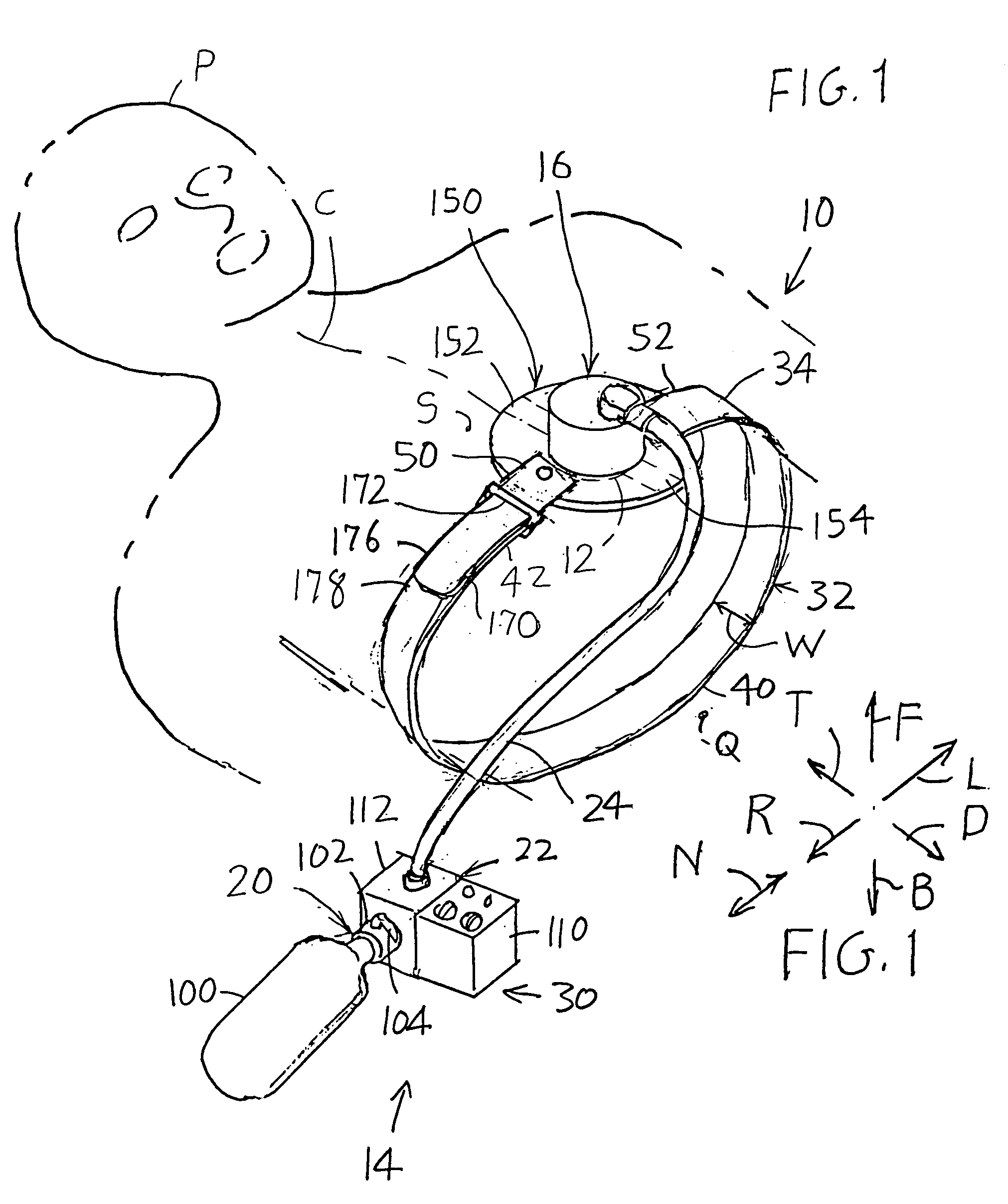
[0012]FIG. 1 illustrates a patient P who has a dangerously low blood circulation such as might occur in a heart attack. An apparatus 10 of the invention includes a compression assembly 14 with a pressing member 12 having a diameter of about three inches, which can be forcefully pushed down against the sternum S of the patient's chest in a series of pulses, to stimulate the heart of the patient. For an adult male patient, the pressing member 12 can press down with a maximum force of about 100 to 120 lbs., in pulses spaced by perhaps ½ to 1 second apart. This mimics the chest compressions applied in CPR (cardiopulmonary resuscitation).

[0013]The compression assembly 14 includes an actuator 16 that forces down the pressing member 12 in pulses, a pressure source 20 that supplies pressured air for energizing the actuator, and a control 22 that controls the application of pressure to the actuator. An elongated flexible tube 24 connects the remote part 30 of the compressor assembly that lie...


PUM


Abstract

Apparatus for compressing the chest of a patient to stimulate blood circulation, includes a torso wrap (32) that has a back portion (40) lying at the back of the patient's chest and a front portion (42) lying at the front of the patient's chest, and includes a compressor assembly with an actuator (16) having a pressing member (12) that can apply a series of force pulses to the sternum of the patient to stimulate blood circulation. The actuator is energized by pressured fluid, with a controlled pressured fluid source (20) connected by an elongated flexible hose (24) to the actuator so the pressured fluid source and a control (22) can lie on the ground and only the actuator lies on the torso wrap. The actuator includes a cylinder (66) and a plurality of telescoping piston parts (64, 66) to provide a long stroke in an actuator of small height. A stabilizer (150) that limits tilt of the actuator from the vertical, includes a saucer-shaped member that presses against the front of the patient.

Description

BACKGROUND OF THE INVENTION[0001]Low systemic profusion is caused by several forms of circulatory shock, including hemorrhage, sepsis, and cardiac arrest, all of which cause large system-wide harm to vital organs. A first mode of damage results from the sudden decrease in oxygen delivery to cells, while a second mode of damage results from the inability to remove cellular waste products such as CO2.[0002]Stimulation of circulation is commonly accomplished by applying pressure pulses to the chest. This can be accomplished by placing a torso wrap around the patient, and attaching a chest compressor to the front of the torso wrap. The actuator applies downward pressure pulses to the patient's chest while the torso wrap holds down the actuator.[0003]In order for a chest compressor system to be widely used, it must be compact and easily attached to the patient. In some cases, a rescuer may be positioned so it is most convenient for him / her to attach the torso wrap by slipping the part wi...

Claims


Application Information

Patent Timeline
Patent Type & Authority Patents(United States)
IPC IPC(8): A61H31/00A61H7/00
CPCA61H31/00A61H31/006A61H1/008A61H2201/5007A61H2031/003A61H2201/1238
Inventor WEIL, MAX HARRYBISERA, JOEYOUNG, CLAYTONTANG, WANCHUN
Owner SUNLIFE SCI INC
Learn More