Marine oil leak recovery and marine petroleum mining method

a technology of marine oil and leak recovery, applied in the field of oil recovery, can solve the problems of billions of dollars in damage to the environment and local businesses, the number of different and expensive techniques, and the immovability or exceeding difficulty of conventional marine oil recovery devices to be transported

Active Publication Date: 2012-05-08
CHE HUE NGUYEN
View PDF13 Cites 46 Cited by
  • Summary
  • Abstract
  • Description
  • Claims
  • Application Information

AI Technical Summary

Benefits of technology

[0011]A vertical and flexible oil flow director hose is used to recover and guide oil spilling from the sea floor to the water surface. Marine water is filtered out of the oil flow director hose because water is denser than oil, and is subject to hydrogen bonding which will draw the water out from the oil flow director hose. Oil is accumulated at the top of said hose, and can be pumped into an oil tanker or into another storage vessel. Meanwhile, gasses from the wellhead are also directed towards the surface by the same director hose, and held above the oil. The gasses are contained in a fixed dome cap, to be compressed into gas tanks on the surface. The oil flow director hose extends all the way from the sea floor to the water surface. The...

Problems solved by technology

Conventional marine oil recovery devices are typically either immovable or exceedingly difficult to transport.
British Petroleum, whose damaged oil well was the source of the Deepwater Spillage, applied a number of different and expensive techniques involving filters and absorbent pads which failed to contain the spillage.
By the time British Petroleum managed to finally cap the wellhead, an estimated 4,900,000 barrels of crude oil had spilled into the Gulf of Mexico, resulting in billions of dollars in damages ...

Method used


Image

  • Marine oil leak recovery and marine petroleum mining method
  • Marine oil leak recovery and marine petroleum mining method
  • Marine oil leak recovery and marine petroleum mining method

Examples


Embodiment Construction

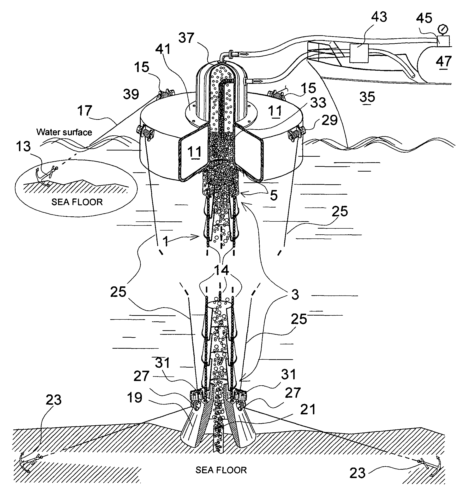
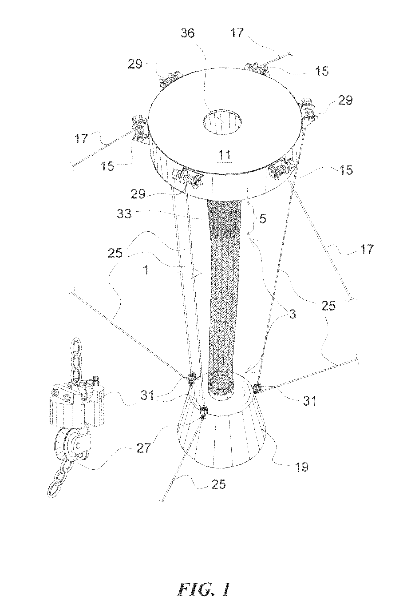
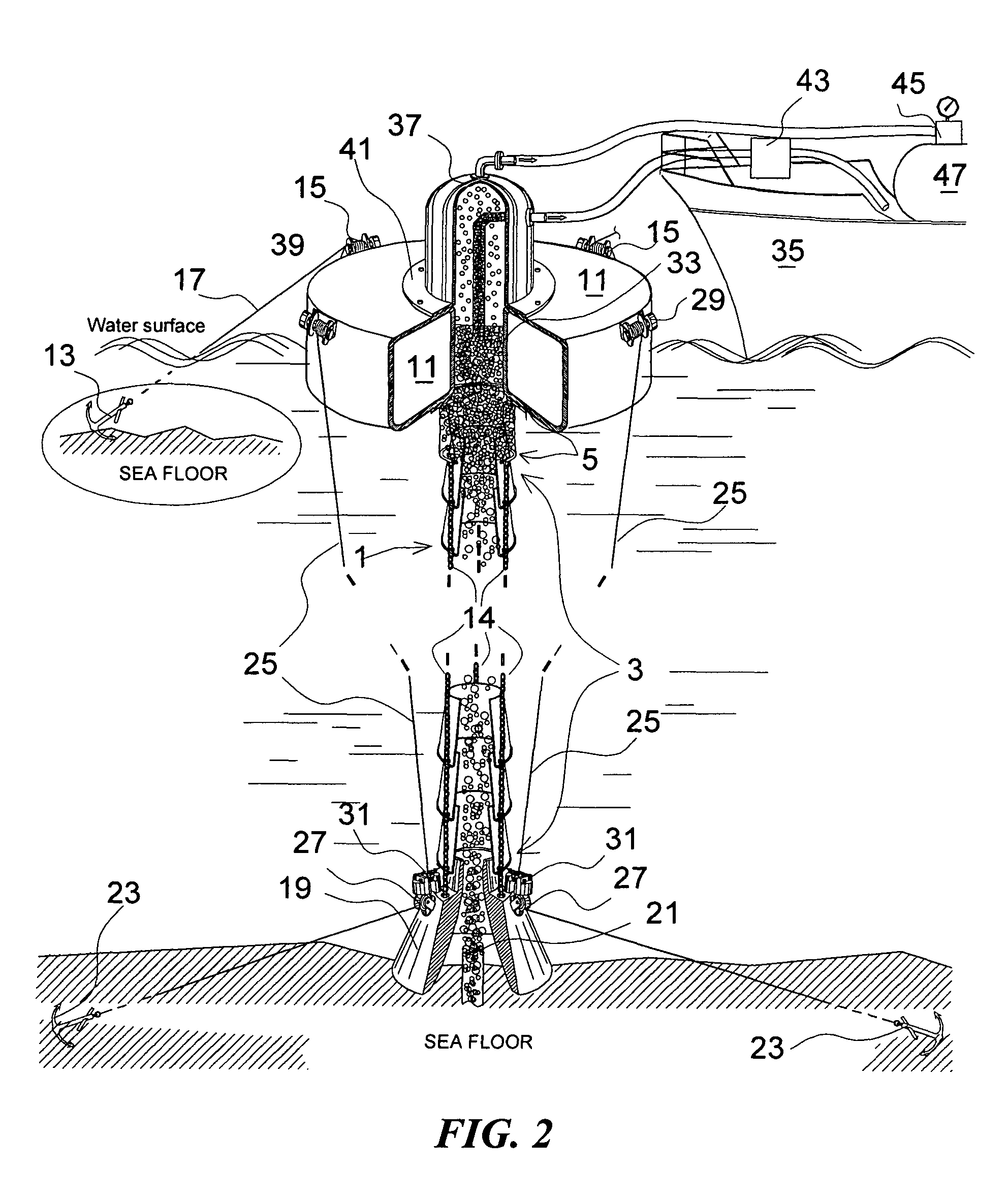
[0048]The present invention provides a method in which mineral and crude oil can be recovered and contained in marine environments and other water-covered areas. The present invention consists of three main parts; which are a vertical flexible oil flow director hose [1], a hollow doughnut-shaped floating device [11], and a toroid sinking weight block [19].

[0049]The vertical flexible oil flow director hose [1] consists of two main portions; the lower portion [3], and the upper portion [5]. The lower portion [3] provides three functions: recovering, directing, and filtering the escaping oil / gas mixture by displacing water out of the said hose. The upper portion [5] provides continuing oil flow direction into the oil accumulator [33], where the oil can be pumped into storage containers.

[0050]The lower portion [3] is a flexible sleeve which is preferably made of woven screen-like fabric. Alternately, the lower portion [3] can also be made of a series of funnel-shaped cones [6] which ove...


PUM


Abstract

A vertical flexible oil flow director hose is used to recover, to guide, and to filter the spilled oil from its source beneath the sea floor to the surface of water and to accumulate the floating oil therein for being ready to be pumped into an oil tanker. The said hose extends in the sea all the way from the sea floor to the surface of water by connecting its lower end to a circular sinking weight block and its upper end to a hollow doughnut-shaped floating device. The said hose includes two main portions abutting each other, the lower portion is for guiding and displacing water out through the gaps or meshes. The upper portion is for continued guiding and accumulating the oil in its upper section. A gas-tight dome cap having an opening at its bottom may be used to cap the upper opening of the oil accumulator well in the floating object, for holding the gas as necessary. A gas-compressor and gas tank or tanks will be equipped on the oil tanker ready to take and to store the gas.

Description

CROSS-REFERENCE TO RELATED APPLICATIONS[0001]Provisional patent application No. 61 / 403,532 which was filed on Sep. 17, 2010.[0002]Non-provisional patent application Ser. No. 12 / 928,236 which was filed on Dec. 7, 2010.STATEMENT REGARDING FEDERALLY SPONSORED RESEARCH OR DEVELOPMENT[0003]Not ApplicableREFERENCE TO SEQUENCE LISTING, A TABLE, OR A COMPUTER PROGRAM LISTING COMPACT DISK APPENDIX[0004]Not ApplicableFIELD OF THE INVENTION[0005]The present invention relates to a simple and inexpensive method for the containment and recovery of leaking mineral or crude oil from the sea floor. Additionally, it provides an easy way to extract marine petroleum from an oil reserve located beneath the sea floor.BACKGROUND OF THE INVENTION[0006]The present invention is in the technical field of oil recovery. More particularly, the present invention is in the technical field of portable oil recovery devices. More particularly, the present invention is in the technical field of portable oil recovery i...

Claims


Application Information

Patent Timeline
IPC IPC(8): C02F1/40E21B43/01
CPCE21B43/0122C02F1/40C02F2101/32C02F2103/08Y10S210/923
Inventor CHE, HUE NGUYEN
Owner CHE HUE NGUYEN
Why Eureka
Try Eureka