
Integrated diffusion oriented combustion chamber
A combustion chamber and guiding technology, applied in the direction of combustion chamber, continuous combustion chamber, combustion method, etc., can solve the problems of increasing engine length and weight, complex structure, shortening length, etc., to ensure outlet temperature distribution, reduce pollution emissions, simplify The effect of matching structure
- Summary
- Abstract
- Description
- Claims
- Application Information
AI Technical Summary
Problems solved by technology
Method used
Image

Examples
Embodiment Construction
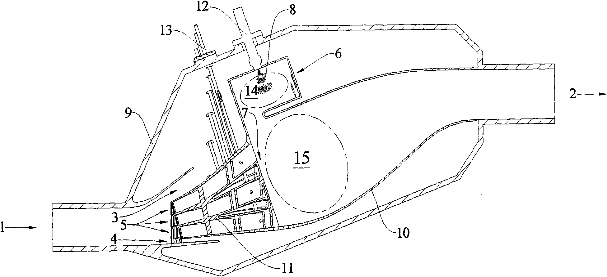
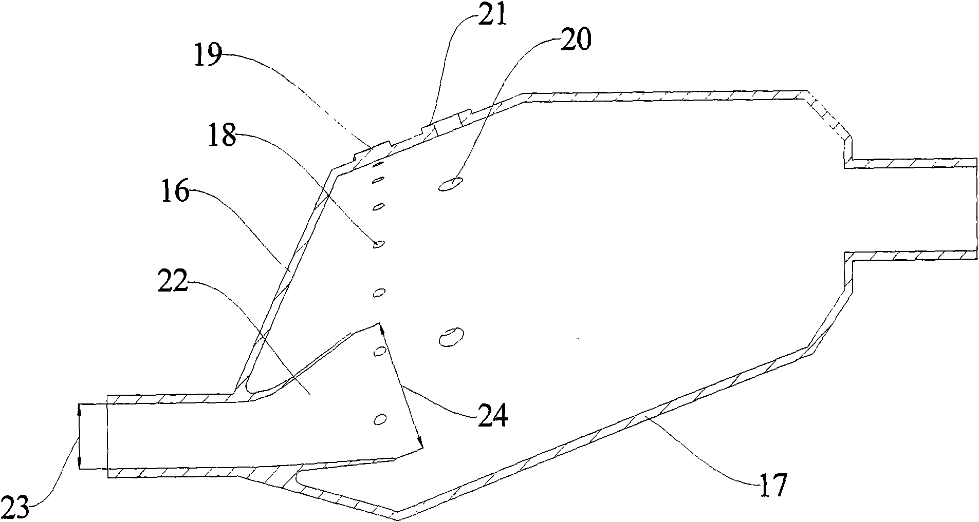
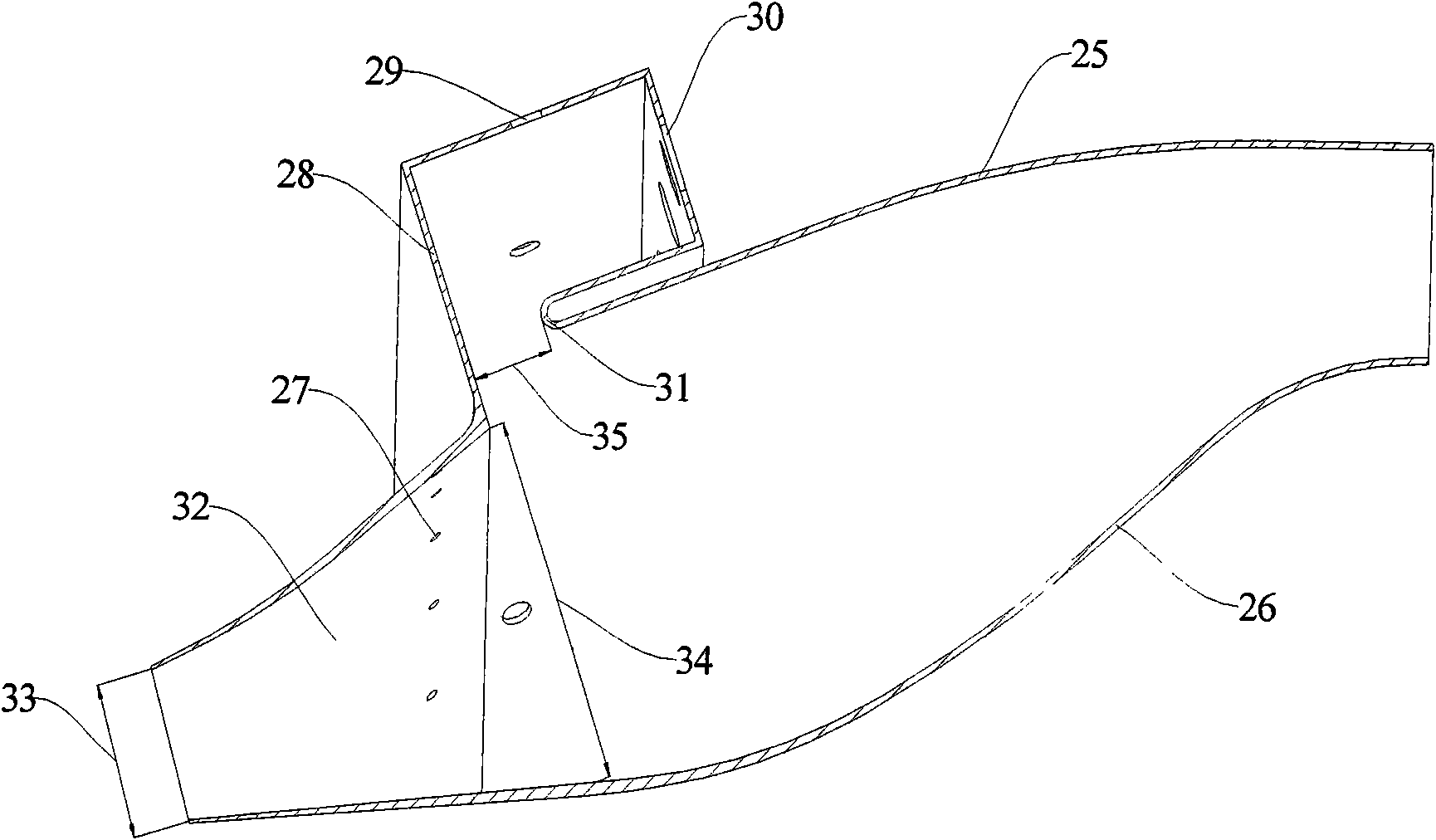
[0029] Such as figure 1 As shown, the invention is structurally mainly composed of a casing 9, a flame tube 10, a guide diffuser 11, a pre-combustion stage fuel injector 12 and a main fuel stage fuel injector 13. The inlet airflow 1 is provided by the compressor, has a certain tangential angle, and is divided into the outer annular cavity airflow 3 , the inner annular cavity airflow 4 and the main combustion stage airflow 5 in the radial direction. The airflow 3 of the outer ring cavity is mainly the cooling of the outer flame tube and the air volume of the pre-combustion level. The air flow 4 in the inner annular cavity is the cooling air for the inner flame cylinder. The pre-combustion level airflow 6 enters the pre-combustion zone 14 to form a trapped vortex flow, which is mixed with the pre-combustion level fuel spray 8 provided by the pre-combustion level fuel injector 12 to form a mixture with an equivalence ratio of 0.6 to 2.0. Forming vortex combustion, the pre-combu...
PUM
 Abstract
Description
Claims
Application Information