
Method and device for reflow soldering with volume flow control

A volume flow and brazing technology, applied in the direction of manufacturing tools, welding equipment, electric solid devices, etc., can solve problems such as increased failure rate, overheating of small parts, etc., to improve temperature distribution, maintain temperature distribution, and high energy utilization efficiency. Effect

Inactive Publication Date: 2009-09-02
REHM THERMAL SYST
View PDF4 Cites 0 Cited by
  • Summary
  • Abstract
  • Description
  • Claims
  • Application Information

AI Technical Summary

Problems solved by technology

When dealing with a large number of different modules, there is a limit to how much the machine can be loaded, as the temperature must be re-tuned for different modules, otherwise if the same settings are used for different modules, there is an increased failure rate due to overheating of small parts danger

Method used


Image

  • Method and device for reflow soldering with volume flow control
  • Method and device for reflow soldering with volume flow control
  • Method and device for reflow soldering with volume flow control

Examples


Embodiment Construction

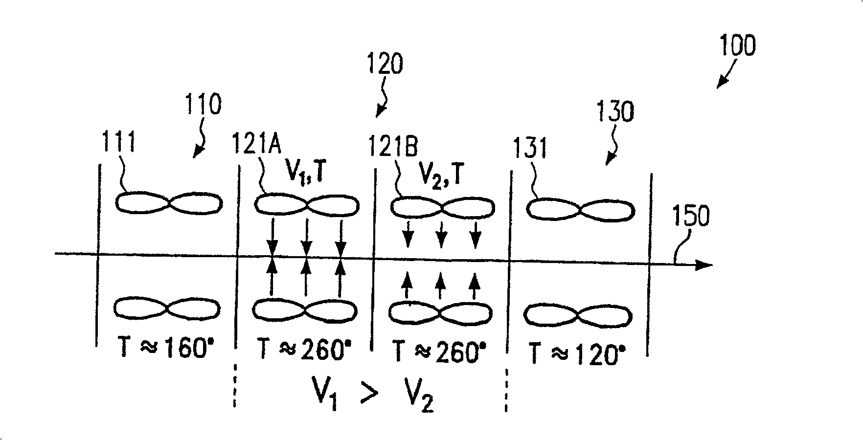
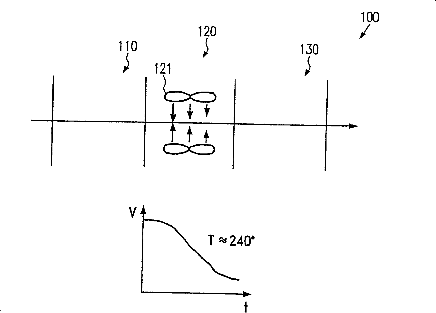
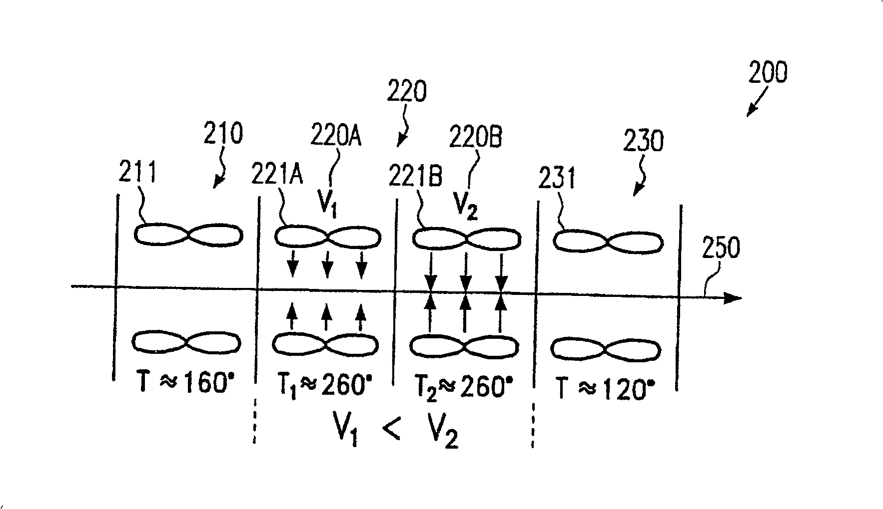
[0032] Figure 1a An example of a reflow soldering apparatus in the form of a transfer furnace 100 is schematically shown. In the example shown, the apparatus comprises at least a preheating zone 110, a brazing zone 120 and a cooling zone 130. In addition, a conveying device 150 is provided which conveys objects to be soldered (not shown), for example in the form of electronic circuit boards with various parts mountable with solder paste, through the respective zones 110 , 120 and 130 . In the example shown, the brazed region 120 is subdivided into two parts 120a and 120b. In section 120a, a volumetric flow of hot gas at a specific temperature T is directed via a first convective heater 121a onto a conveying device 150, or onto an object to be brazed thereon. Similarly, the brazing section 120b includes a convection heater unit 121b which directs a predetermined volume flow of hot gas at a specific temperature T onto the delivery device 150 or optionally onto the objects to b...


PUM


Abstract

According to one aspect of the invention, it is possible to effectively prevent overheating of small parts by rapidly heating the objects to be brazed by reducing the initially large volume flow at a constant or elevated temperature. By utilizing the volume flow of the convection heater to control the effective heat transfer that takes place on the objects to be brazed, it is also possible to adapt the brazing process extremely flexibly to specific process requirements due to the regulation of the changed volume flow can be controlled very quickly and precisely.

Description

technical field [0001] The present invention relates to a method and apparatus for reflow soldering, in which the objects to be brazed, assembled with parts, are subjected to a specific brazing in which a solder paste in contact with the parts at specific points is preheated It is then liquefied in the brazing zone to establish the desired brazing contact. Background technique [0002] During the industrial mass production of modules with electronic components, it is often necessary to solder a large number of temperature-sensitive components to corresponding contact pads on the circuit board. For this purpose, the electronic part includes a suitable solder surface, which for a usual part is a wire connection or a contact pin, or in the case of a surface mounted part (SMD part) at an appropriate point. form of metal surface. As modules become increasingly miniaturized, individual parts continue to get smaller. The form of the part and its use partly imply a certain minimu...

Claims


Application Information

Patent Timeline
Patent Type & Authority Patents(China)
IPC IPC(8): H05K3/34B23K1/008
CPCH01L2924/0002H05K2203/1476H05K2203/081B23K1/008H05K3/3494H05K2203/111B23K2201/40B23K2101/40H01L2924/00H05K3/34
Inventor 汉斯·贝尔
Owner REHM THERMAL SYST
Learn More