
Sliding slot heat treatment device

A heat treatment device and heat treatment chamber technology, applied in lighting and heating equipment, furnace components, furnace types, etc., can solve the problems of high heat treatment device height and hot gas leakage.

Inactive Publication Date: 2005-09-21
ESPEC CORP
View PDF4 Cites 0 Cited by
  • Summary
  • Abstract
  • Description
  • Claims
  • Application Information

AI Technical Summary

Problems solved by technology

However, since the gate is raised and lowered only by the height of the entire floor of the frame, there is a problem that the height of the heat treatment device becomes higher as in the gondola lifting type device.
In addition, the open gap is always connected to the outside, and there is often hot air leakage, and there is the same problem of hot air leakage as in Patent Document 3 when the gate is raised and lowered.

Method used


Image

  • Sliding slot heat treatment device
  • Sliding slot heat treatment device
  • Sliding slot heat treatment device

Examples


Embodiment Construction

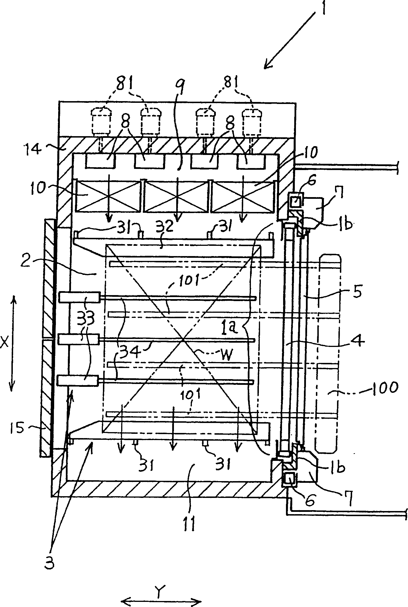
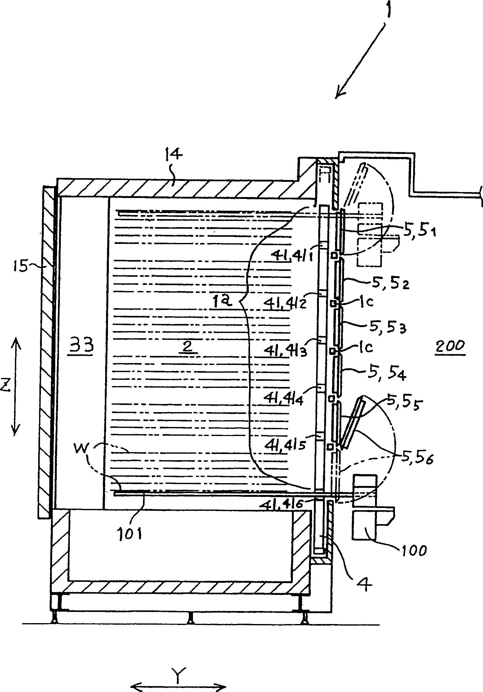
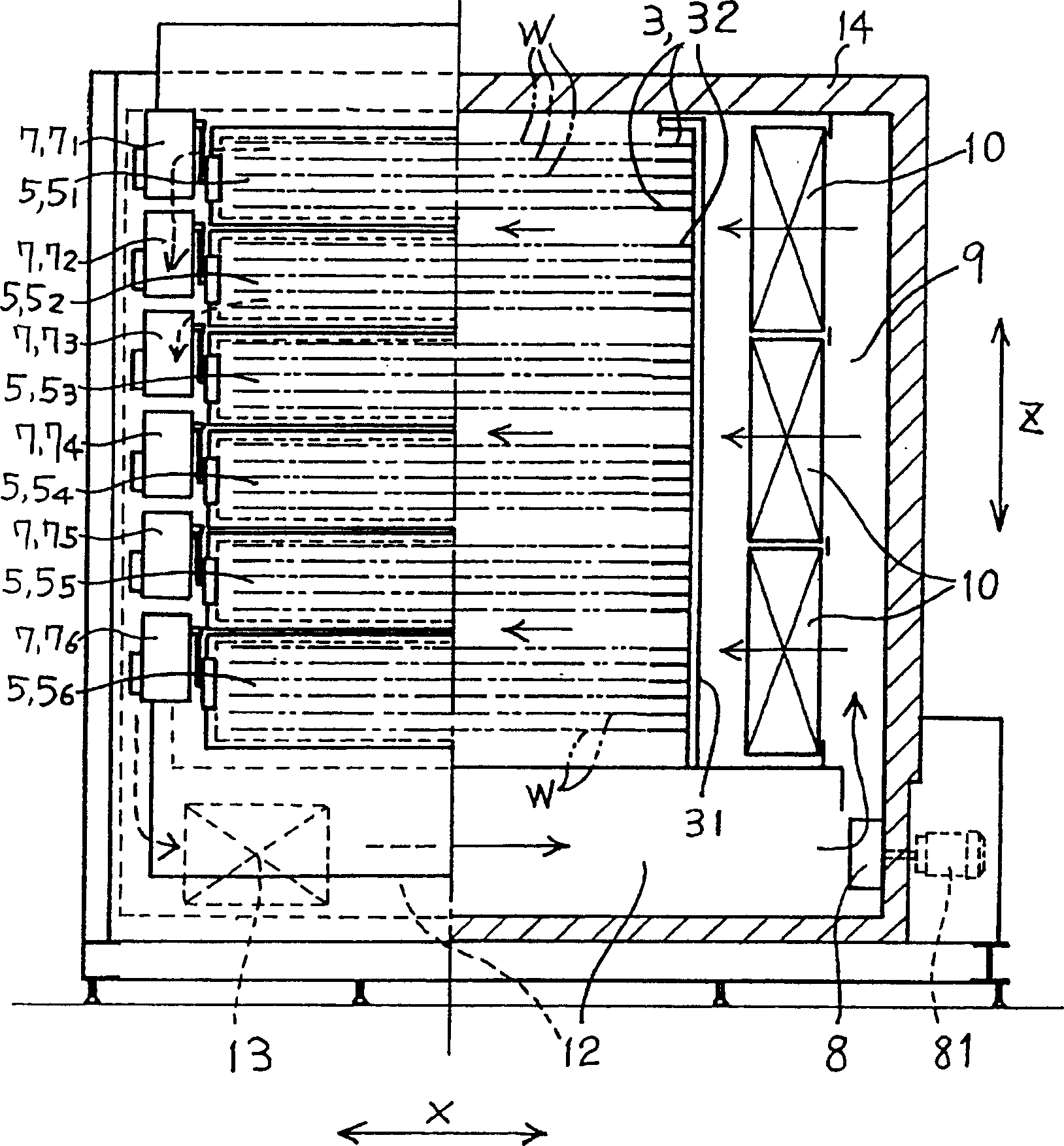
[0030] Figure 1 ~ Figure 3 An example of the overall structure of a heat treatment apparatus commonly called a purification furnace as a heat treatment apparatus to which the present invention is applied is shown.

[0031] The heat treatment apparatus 1 is a kind of workpiece W such as a glass substrate that is processed in a LCD substrate or a PDP manufacturing flow as a flat plate-shaped object to be processed with a support body 3 as a support device installed in the heat treatment chamber 2. , and from the opening face 1a that is formed on one side of the heat treatment chamber as the opening of the heat treatment chamber 2 in this example to take and place the device for heat treatment one by one, wherein as a multilayer, it is 31 layers in this example, and it has as a slit The shielding plate 4, the small door 5, the lifting mechanism 6, and the opening and closing mechanism 7 of the parts.

[0032] There are air-conditioning parts on both sides of the width X directi...


PUM


Abstract

A thermal treatment unit 1 is a device for carrying out a thermal treatment of a works W by supporting the works W on supporting frames of the unit 1 to multi-stages as 31 stages and taking in and out the works w. The unit comprises an isolating plate 4 fitted with 6 slits 41 of 411 to 416, small doors 5 divided in 6 pieces of 51 to 56 to open and close the slits, an up and down device 6 for the plate 4, an open and close device 7 for the small doors 5, etc. The work W is put in and out without leakage of hot air in a thermal treatment room 2 by opening, for example, only the door 56 maintaining the other small doors closed when putting in and out the work W through the slit 46. A height of the unit is kept low as the plate 4 moves vertically only the distance corresponding to 5 stages of the works.

Description

technical field [0001] The present invention relates to a sliding slit type that supports multi-layer plate-like objects to be processed on a support device provided in a heat treatment chamber, and takes and places the objects to be processed one by one from the opening of the heat treatment chamber for heat treatment. Heat treatment device. Background technique [0002] As a heat treatment device generally called a purification furnace, which supports flat workpieces such as multi-layer LCD glass substrates in a heat treatment chamber, and takes them one by one for heat treatment, the structure that is generally used in the past is to install workpieces at a certain position. The slit-shaped opening of the machine is loaded with multi-layer workpieces at certain intervals on a loading device called a gondola (condola), which can be lifted. The lifting gondola aligns the position of the workpiece after heat treatment with the opening, and then picks and places it with a man...

Claims


Application Information

Patent Timeline
Patent Type & Authority Patents(China)
IPC IPC(8): F27B17/00C03B27/044F27B9/30F27D1/18F27D3/12
CPCC03B29/025F27B9/30
Inventor 田中秀树
Owner ESPEC CORP
Learn More