Installation for producing electrical energy provided with means of energy storage and control method of such an installation

a technology for installing and producing electrical energy, which is applied in the direction of emergency power supply arrangements, process and machine control, instruments, etc., and can solve the problems of limiting the reaction time and general degradation of the battery over tim

Active Publication Date: 2014-08-28
GE INFRASTRUCTURE TECH INT LLC
View PDF10 Cites 13 Cited by
  • Summary
  • Abstract
  • Description
  • Claims
  • Application Information

AI Technical Summary

Benefits of technology

[0029]In view of the foregoing, the invention aims to increase the responsiveness, flexibility and reliable operation of electricity generating plants connected to networks with the characteristics listed above.
[0033]The integration of storage means allows their use as a providing medium to meet the demand of peak starting current of the gas turbine. Indeed, the storage means to reduce the rated power may even eliminate duplication of generators needed to start.
[0051]Preferably, the energy storage means are able to support starting the system, thus limiting the calls to the networks or current generators after stopping of the network.

Problems solved by technology

Furthermore, the degradation of the battery over time is generally due to the extent that this degradation occurs at each cycle of loading and unloading (hysteresis).
Another problem is the reaction time of these means of storage and generation, limiting the reaction time to limit the impact of fault on the network and the plant.

Method used


Image

  • Installation for producing electrical energy provided with means of energy storage and control method of such an installation
  • Installation for producing electrical energy provided with means of energy storage and control method of such an installation
  • Installation for producing electrical energy provided with means of energy storage and control method of such an installation

Examples


Embodiment Construction

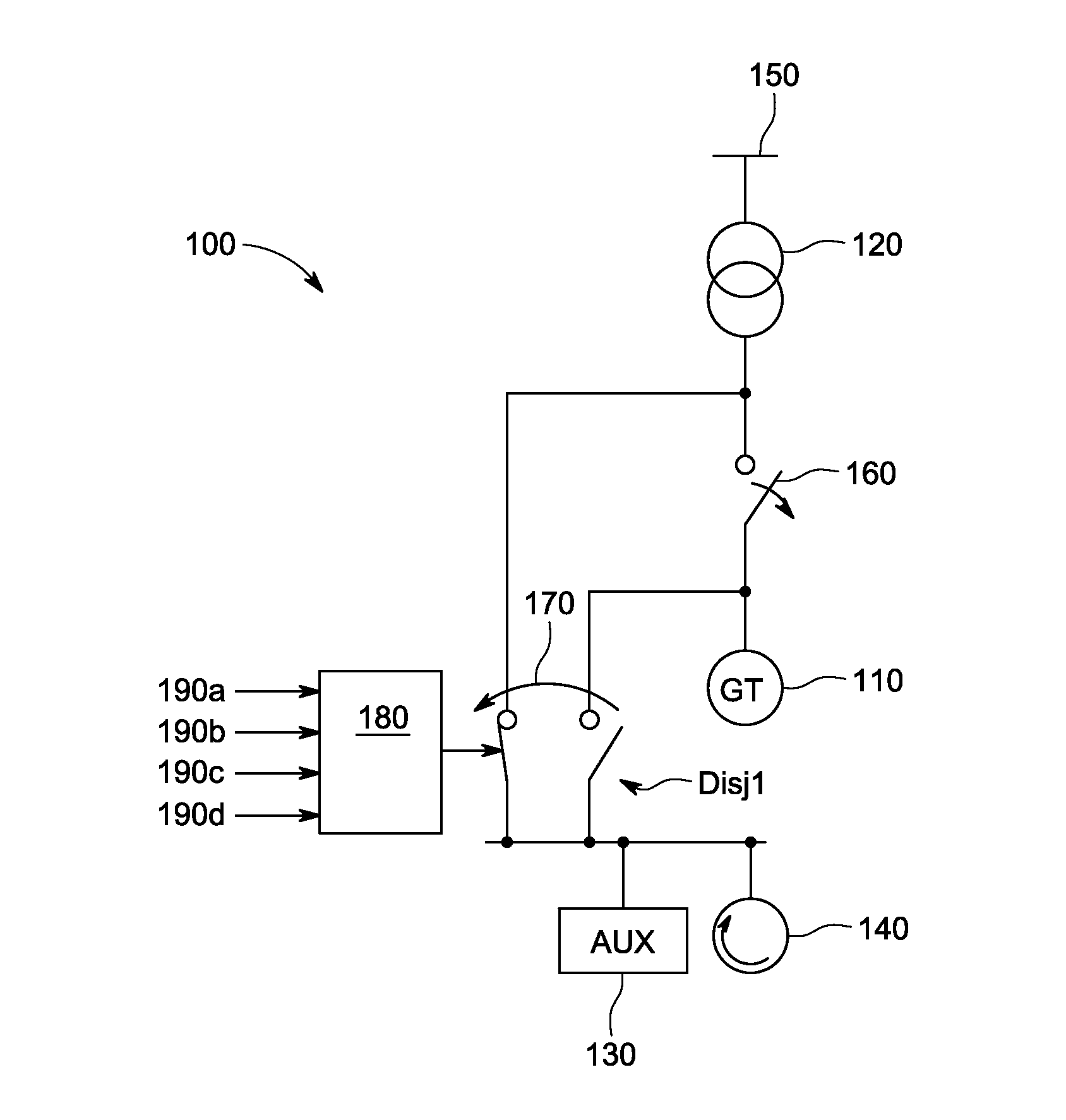
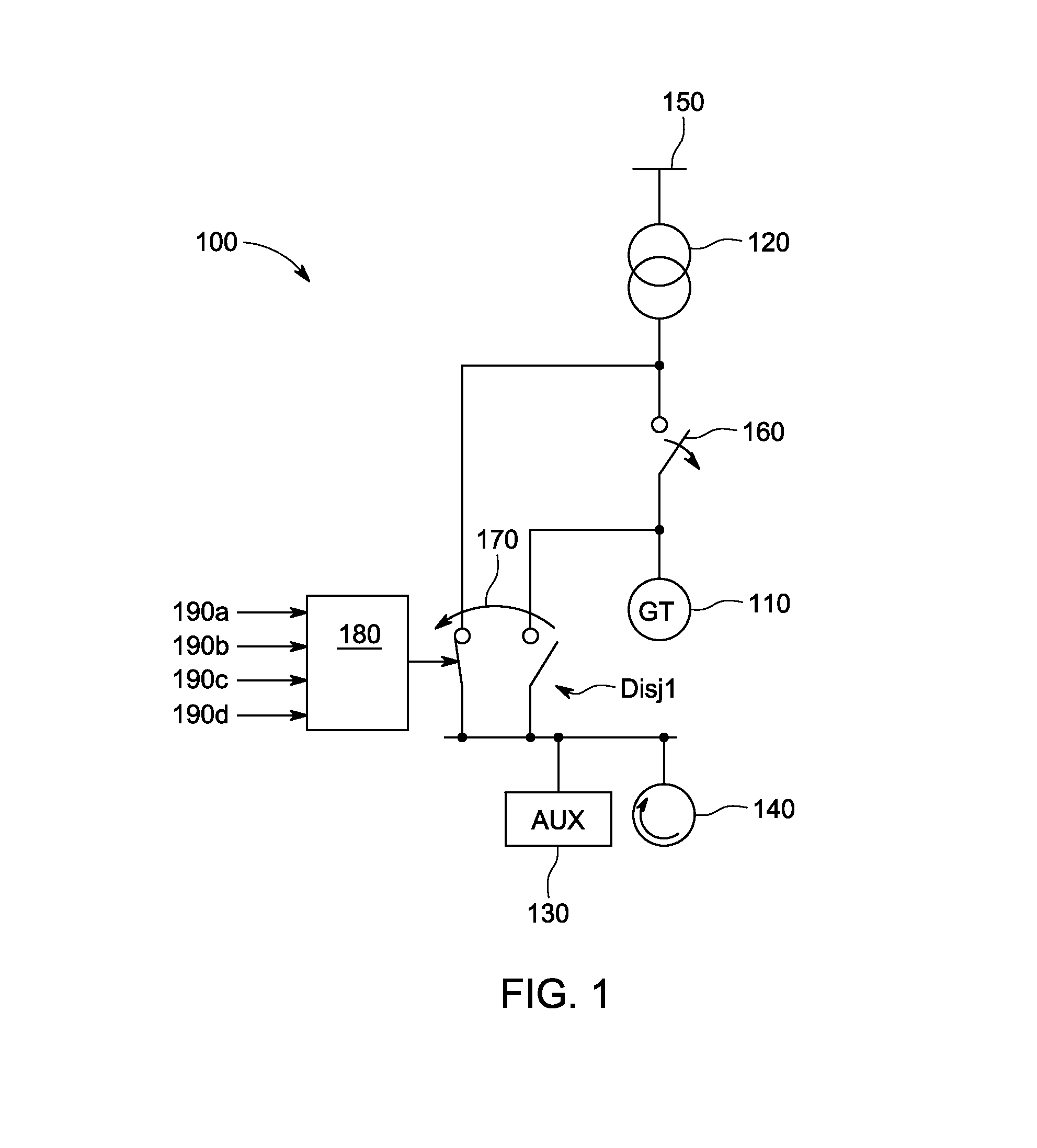
[0063]Referring first to FIG. 1, the architecture of a plant for producing electrical energy (central power generation system 100) is described according to an embodiment of the invention. As shown in FIG. 1, which includes a portion of a central power generation system 100 with a gas turbine 110 or combined cycle, such a production facility includes an electric power generator, for example a gas turbine 110 coupled to an alternator and connected to a distribution network 150 by means of a transformer 120. During normal operation of the plant, the generator delivers electrical power to the grid. When starting, the generator operates in motor mode and draws energy on the network to drive the turbine. The facility is also equipped with auxiliary systems 130, of various kinds, ensuring the execution of accessory functions, including lubrication pumps and cooling fan motor, power supply circuits of the turbine fuel, and a valve assembly.

[0064]The facility is also equipped with a means o...


PUM


Abstract

An installation for producing electrical energy is provided with an energy storage means and a control method of such an installation. The installation includes an electrical energy generator that connects to a distribution network and the energy storage means. The installation also comprises a controller controlling the operation of the energy storage means and the connection of the energy storage means to the electrical energy generator and the network. The controller receives a set of information from the network or, energy storage means, and the electrical energy generator, and from the network manager to control the supply of the electrical energy generator and a set of auxiliary equipment of the installation from the energy storage means in the event of power failure.

Description

CROSS REFERENCE TO RELATED APPLICATIONS[0001]This application claims the benefit of priority of PCT Application No. PCT / IB2012 / 02861 filed Nov. 16, 2012, which claim the benefit of priority of European Patent Application Serial No. 11306522.1, entitled “Installation For Producing Electrical Energy Provided With Means Of Energy Storage And Control Method Of Such An Installation,” filed Nov. 18, 2011, both disclosures of which are incorporated herein by reference in its entirety.BACKGROUND OF THE INVENTION[0002]Combined cycle electric power generation uses a gas turbine and a steam turbine. In production facilities, electric energy is currently based primarily on the use of hydroelectric, nuclear and fossil large-scale electricity supply systems via transmission and distribution. Reduction targets of CO2 emissions set in many countries, will bring an increase in the share of renewable energy that will reach, by 2020, 35% in Germany and 20% in France, for example. In addition to increa...

Claims


Application Information

Patent Timeline
Patent Type & Authority Applications(United States)
IPC IPC(8): G05F1/10
CPCG05F1/10F02C1/00F02C6/14H02J3/30H02J9/066Y02B10/70Y02B70/30Y02E60/16Y02T50/60Y04S20/20H02J3/38H02J7/34
Inventor PENA, EZIOBIELLMANN, HERVEBUQUET, MAXIMECHEVALIER, FREDERICCHILLAR, RAHUL JAIKARANGUYOT, JULIENINGREMEAU, JEAN MARCVIGNOLO, JEAN-LOUIS
Owner GE INFRASTRUCTURE TECH INT LLC
Why Eureka
Try Eureka