Supercharge Your Innovation With Domain-Expert AI Agents!

Photovoltaic module and method for manufacturing same

a photovoltaic module and photovoltaic technology, applied in the field of photovoltaic modules, can solve problems such as the possibility of cell division or electrode peeling

Inactive Publication Date: 2014-09-04
PANASONIC INTELLECTUAL PROPERTY MANAGEMENT CO LTD
View PDF0 Cites 3 Cited by
  • Summary
  • Abstract
  • Description
  • Claims
  • Application Information

AI Technical Summary

Benefits of technology

The patent describes a structure that uses a connection member with unevenness on the surface opposite to the back surface of a photovoltaic element. When this connection member is pressed against the photovoltaic element with adhesive in between, the unevenness helps to remove any excess adhesive between the two surfaces, ensuring a proper connection. This design improves the efficiency and reliability of photovoltaic devices.

Problems solved by technology

This document also describes that, in the soldering of the bus bar and the tab, there is a possible risk of cell division or electrode peeling.

Method used


Image

  • Photovoltaic module and method for manufacturing same
  • Photovoltaic module and method for manufacturing same
  • Photovoltaic module and method for manufacturing same

Examples


Embodiment Construction

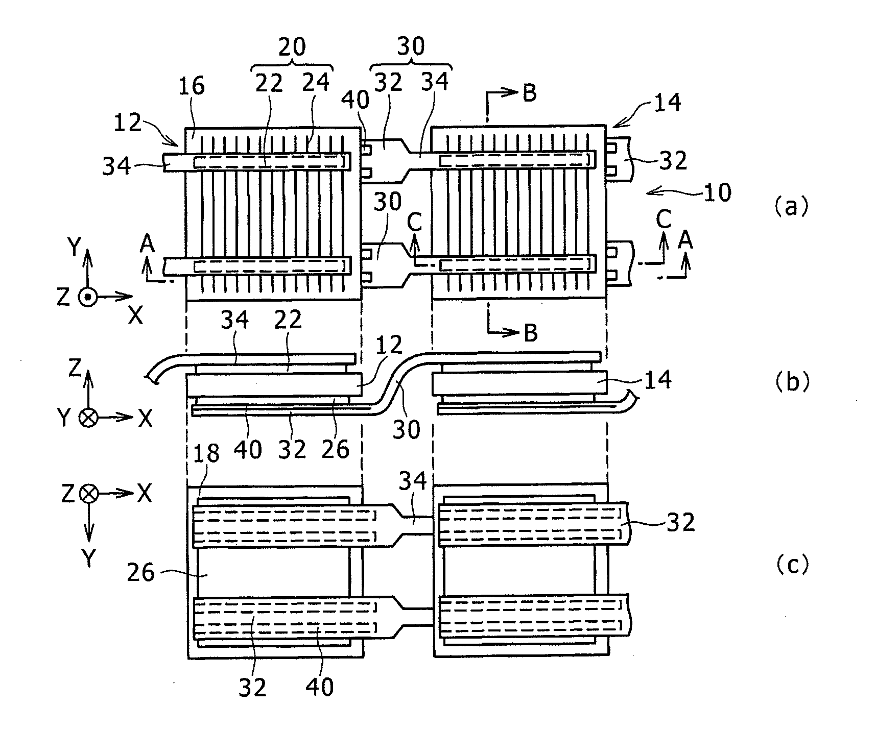
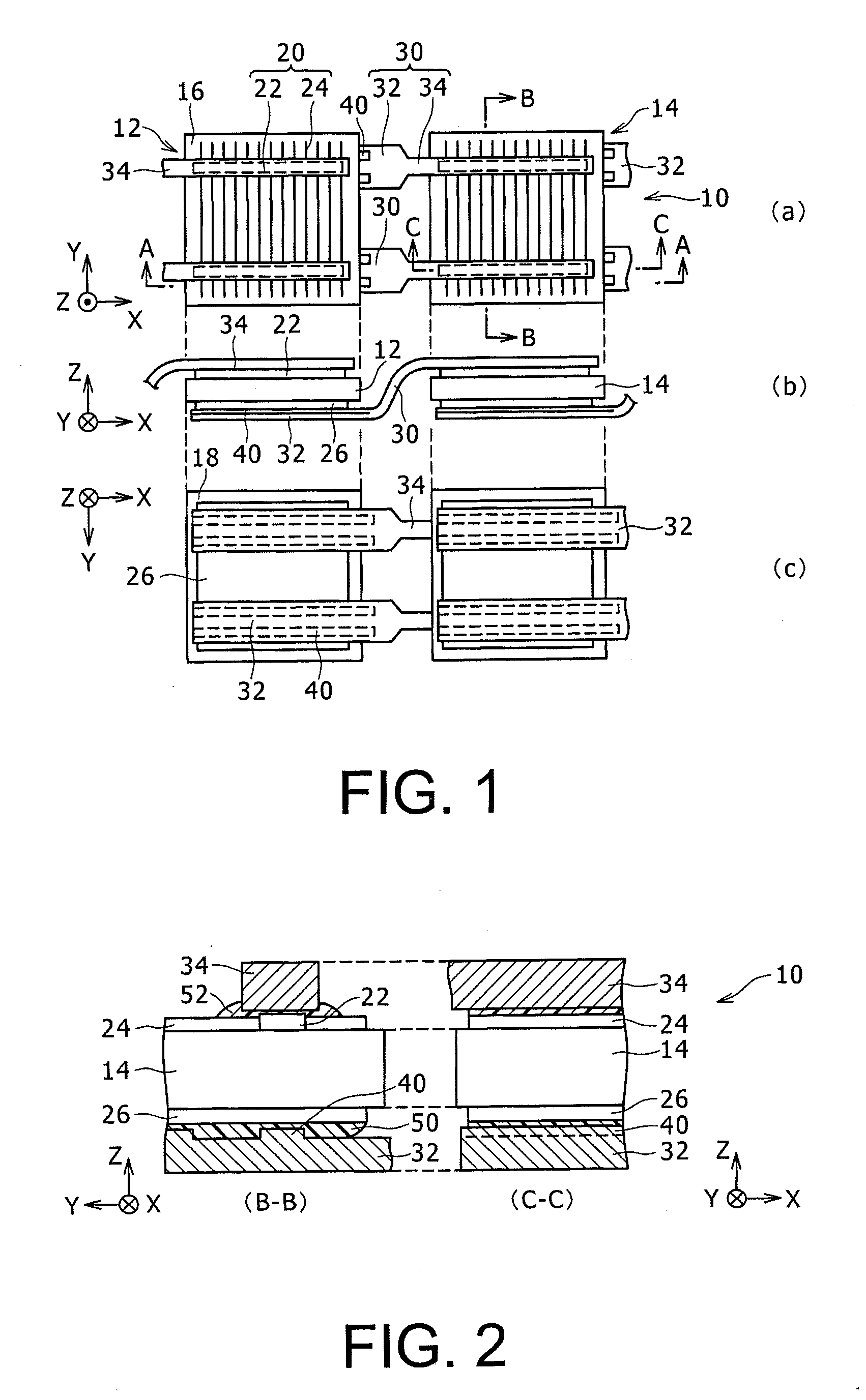
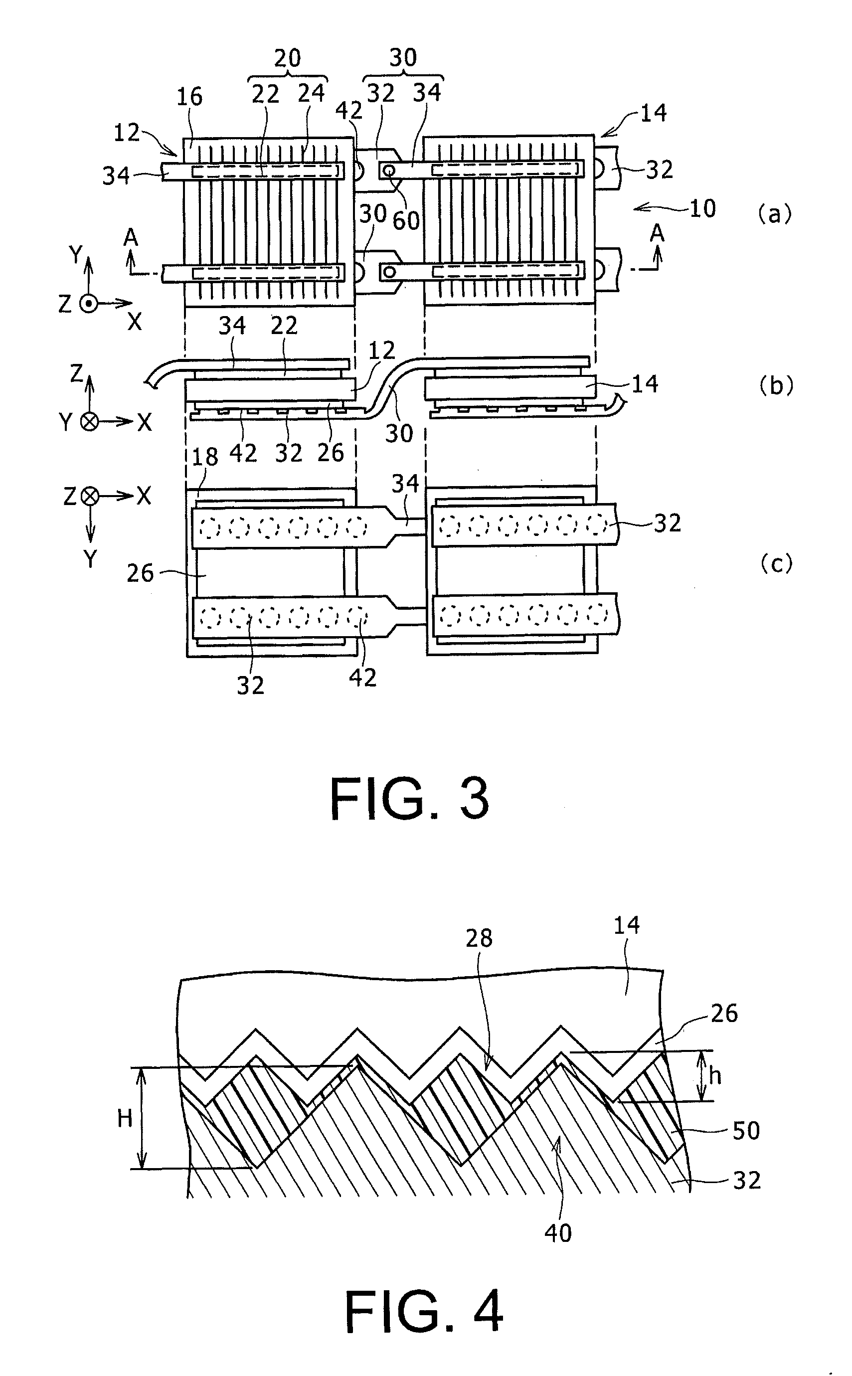
[0021]A preferred embodiment of the present invention will now be described in detail with reference to the drawings. In the following, an electrode having a bus bar and a finger will be described as a light receiving surface-side electrode of a photovoltaic element, but alternatively, the electrode may have only the finger. In the following, a square shape will be described as the planar shape of the photovoltaic element, but alternatively, the planar shape may be other shapes such as rectangular and circular.

[0022]A shape, a size, a number and a material of the electrode, or the like described in the following are merely exemplary for the purpose of the explanation, and may be suitably changed according to the specification of the photovoltaic element.

[0023]In the following, the same reference numerals will be assigned to the same elements among all drawings, and the elements will not be repeatedly described. In addition, in the description herein, reference numerals that are alre...


PUM


Abstract

A photovoltaic module (10) is provided with: photovoltaic elements (14), each of which has a light receiving surface-side electrode and a back surface-side electrode (26); and a connection member which is connected to the photovoltaic elements (14) with resin-containing adhesive layers (50, 52) respectively interposed therebetween. The width of the connection member facing the back surface-side electrode (26) is narrower than the width of the back surface-side electrode (26). The connection member has recesses and projections (40) on the surface facing the back surface-side electrode (26), and connects one photovoltaic element and another photovoltaic element (14) with each other, said photovoltaic elements being arranged adjacent to each other. The back surface-side electrode (26) is an electrode that covers generally all over the back surface of the photovoltaic element (14).

Description

CROSS-REFERENCE TO RELATED APPLICATIONS[0001]The present application is a continuation under 35 U.S.C. §120 of PCT / JP2011 / 077638, filed Nov. 30, 2011, which is incorporated herein by reference.[0002]1. Technical Field[0003]The present invention relates to a photovoltaic module in which adjacent photovoltaic elements are connected by a connection member, and a manufacturing method thereof.[0004]2. Background Art[0005]In a photovoltaic element which generates power by receiving solar light, an electrode for collecting electricity is provided on a surface which is called a primary surface, in order to extract electrical power from a photovoltaic unit which generates an electromotive force by receiving the solar light. In order to have a photovoltaic module by connecting a plurality of photovoltaic elements to each other, the electrodes of the adjacent photovoltaic elements are connected to each other by a connection member.[0006]For example, Patent Document 1 discloses that, in a solar...

Claims


Application Information

Patent Timeline
Patent Type & Authority Applications(United States)
IPC IPC(8): H01L31/05
CPCH01L31/0516H01L31/0508Y02E10/52H01L31/056
Inventor YOSHIMINE, YUKIHIRO
Owner PANASONIC INTELLECTUAL PROPERTY MANAGEMENT CO LTD
Features
  • R&D
  • Intellectual Property
  • Life Sciences
  • Materials
  • Tech Scout
  • Unparalleled Data Quality
  • Higher Quality Content
  • 60% Fewer Hallucinations
Learn More