Supercharge Your Innovation With Domain-Expert AI Agents!

Method for retrofitting a gas turbine power plant

Inactive Publication Date: 2015-02-05
SIEMENS AG
View PDF14 Cites 0 Cited by
  • Summary
  • Abstract
  • Description
  • Claims
  • Application Information

AI Technical Summary

Benefits of technology

The patent describes a method for reducing carbon dioxide emissions from a power plant. The method involves using a steam generating unit to transfer heat from the plant to a CO2 separation apparatus, which then removes the carbon dioxide from the flue gas. The separated carbon dioxide can be sold to the oil extraction industry, allowing for a direct and cost-effective supply. Connecting the CO2 separation apparatus to a CO2 supply network further improves the efficiency and affordability of the process.

Problems solved by technology

Over recent years, it has been proved, however, that the costly transporting of CO2 produced in this way from the refinery sites to the oil deposits requires a sometimes large and expensive piping network.
The provision of such a network, however, in turn greatly increases the costs for the CO2 and therefore the costs for the crude oil which is extracted with the aid of the CO2.
This additional consumption of energy on the one hand reduces the cost effectiveness of the CO2 which is produced in this way and, in addition, also appreciably reduces the overall efficiency of the system consisting of combustion system and CO2 separation apparatus.

Method used


Image

  • Method for retrofitting a gas turbine power plant
  • Method for retrofitting a gas turbine power plant
  • Method for retrofitting a gas turbine power plant

Examples


first embodiment

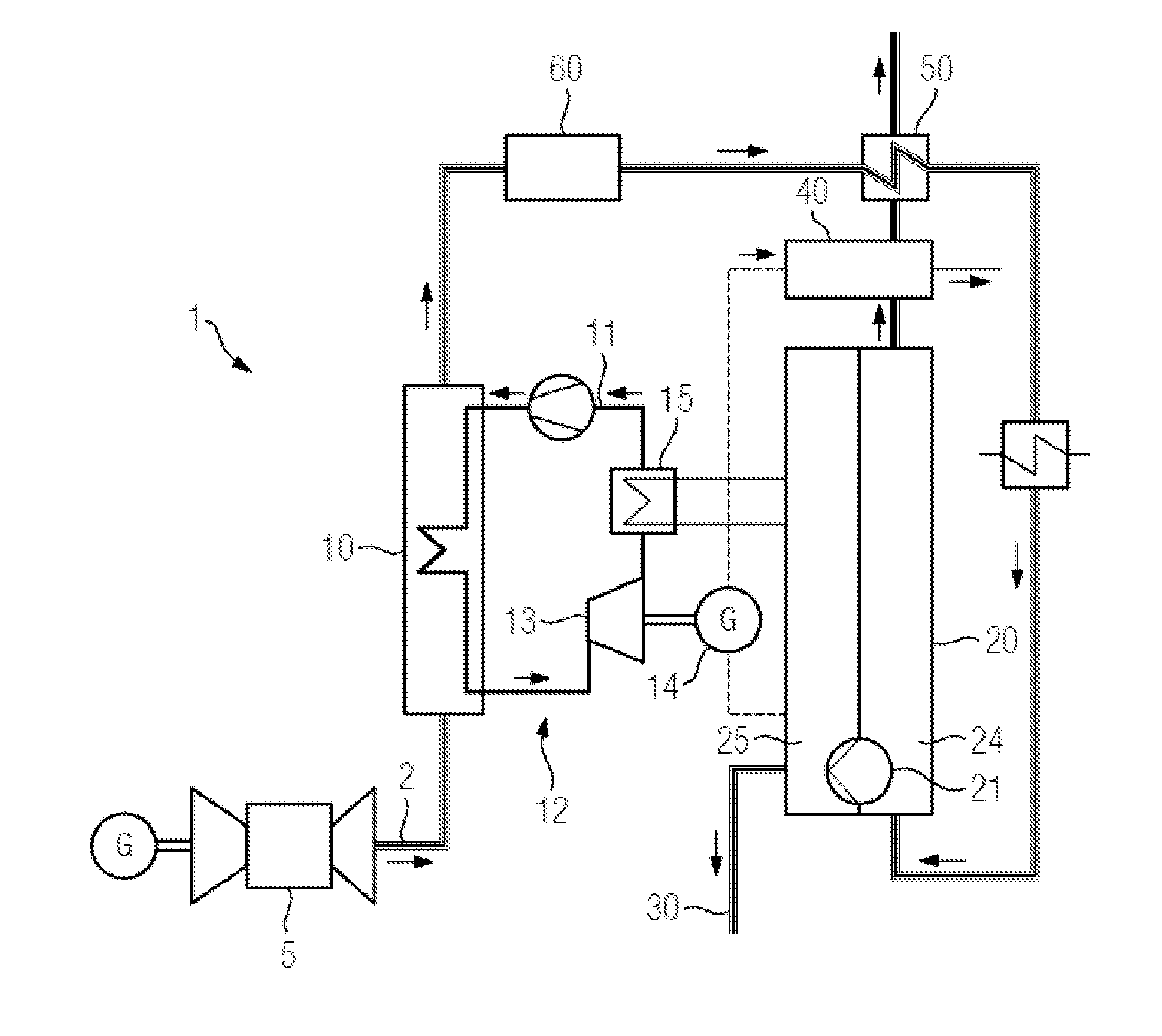
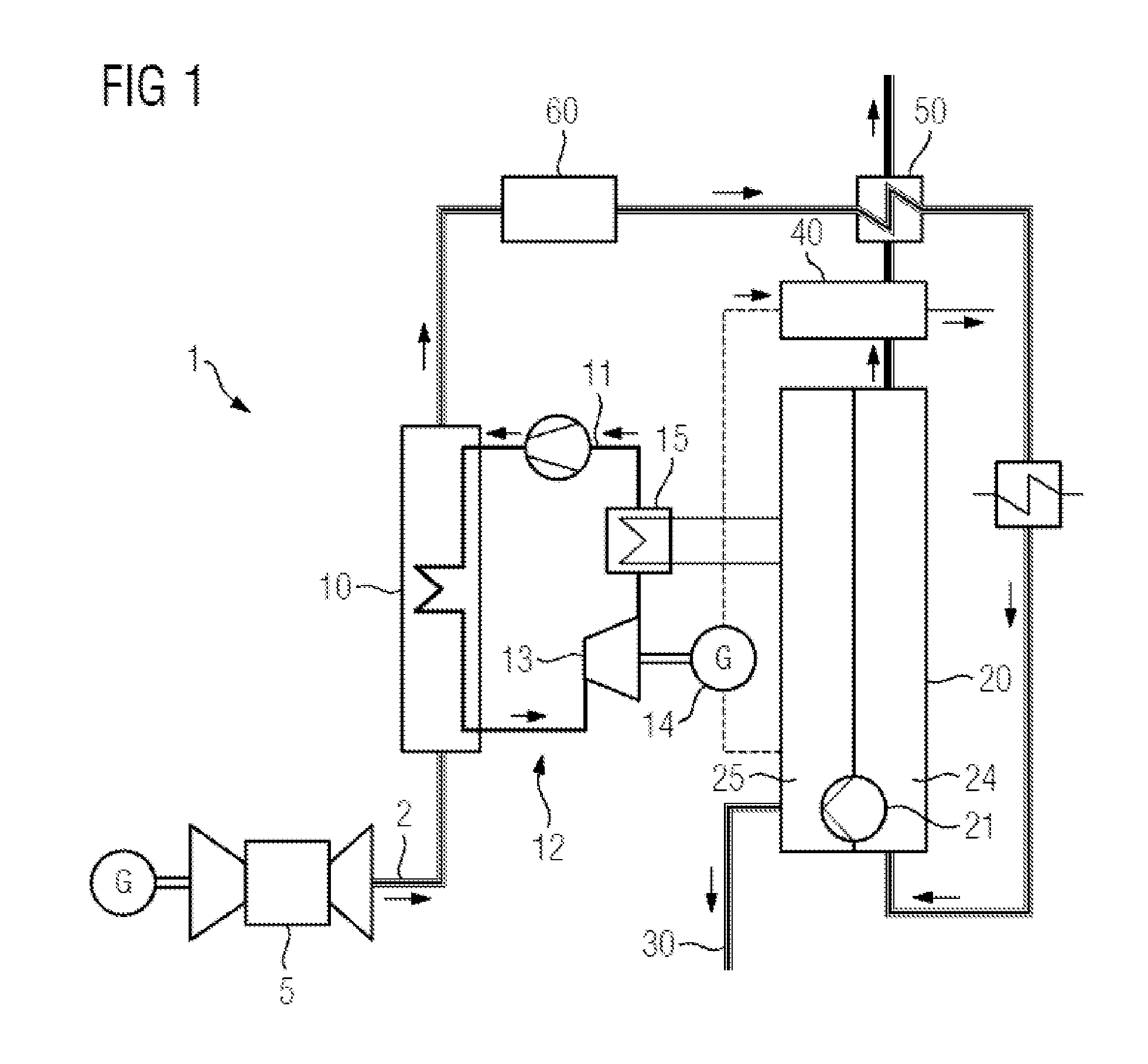
[0040]FIG. 1 shows a system, having gas turbine 5 and CO2 separation apparatus, which is created by means of the method according to the invention for retrofitting an already existing gas turbine power plant 1. To this end, a flue gas duct 2 has been connected to a gas turbine 5 and is suitable for discharging the flue gas which issues from the gas turbine 5. The flue gas is directed by means of the flue gas duct 2 to a steam generating unit 10 which by means of thermal contact extracts thermal energy from the flue gas and transfers this thermal energy to a water-steam cycle 11. The fluid flow in the water-steam cycle 11 is maintained by a pump (not provided with a designation in the present case) and after passing through the steam generating unit 10 is fed to a back-pressure turbine 13. By expansion in the back-pressure turbine 13 and also by release of thermal energy for providing mechanical energy in the back-pressure turbine 13, a generator 14, connected to said back-pressure t...


PUM

PropertyMeasurementUnit
Energyaaaaaaaaaa
Power outputaaaaaaaaaa

Abstract

A method for retrofitting an already existing gas turbine power plant is provided. The method features at least the following steps: fluidically connecting a gas turbine to a flue gas duct which is suitable for conducting flue gas which is produced by the gas turbine; connecting the flue gas duct to a steam generating unit which is fluidically connected to a water-steam cycle, and via which water-steam cycle a power generating facility can be operated; fluidically connecting a CO2 separation apparatus to the flue gas duct for separating the CO2 from the flue gas in the flue gas duct; and electrically connecting the power generating facility to the CO2 separation apparatus, preferably for the essentially energy-autonomous operation of the CO2 separation apparatus.

Description

CROSS REFERENCE TO RELATED APPLICATIONS[0001]This application is the US National Stage of International Application No. PCT / EP2012 / 075199 filed Dec. 12, 2012, and claims the benefit thereof. The International Application claims the benefit of German Application No. 102012208221.2 filed May 16, 2012 and German Application No. 102012202729.7 filed Feb. 22, 2012. All of the applications are incorporated by reference herein in their entirety.FIELD OF INVENTION[0002]The present invention relates to a method for retrofitting an already existing gas turbine power plant which is to be equipped with a CO2 separation apparatus.BACKGROUND OF INVENTION[0003]The separation of CO2 gas from an exhaust gas low of a combustion system allows a reduced emission of CO2 into the atmosphere. This, especially against the background of state and interstate regulated reductions of emitted CO2, is an economical cost factor which is increasingly taken into consideration in the commercial future plans of many ...

Claims


Application Information

Patent Timeline
IPC IPC(8): B23P19/04
CPCB23P19/042F23J15/04F23J15/06F23J2215/50F23J2219/40F23J2219/70Y10T29/49229Y02E20/30F02C6/18
Inventor BRUNHUBER, CHRISTIANKREMER, HERMANNSTROBELT, FRANKVORTMEYER, NICOLASZIMMERMANN, GERHARD
Owner SIEMENS AG
Features
  • R&D
  • Intellectual Property
  • Life Sciences
  • Materials
  • Tech Scout
  • Unparalleled Data Quality
  • Higher Quality Content
  • 60% Fewer Hallucinations
Learn More