DC squid based RF magnetometer operating at a bandwidth of 200 mhz and higher

a rf magnetometer and squid technology, applied in the field of magnetic measurements, can solve the problems of affecting the signal integrity and detectability, affecting the application of capacitive and/or inductive near-field coupling of squids, and open loop operation

Active Publication Date: 2014-09-04
NEOCERA
View PDF8 Cites 9 Cited by
  • Summary
  • Abstract
  • Description
  • Claims
  • Application Information

AI Technical Summary

Benefits of technology

[0017]It is another object of the present invention to provide an RF magnetometer based on the DC SQUID in which the FLL (flux-locked loop) bandwidth limitations are overcome by using a flux-locked loop that locks the static flux and creates AC bias for the RF flux at the maximum slope of the VA) function of the DC SQUID.
[0018]It is a further object of the present invention to provide a DC SQUID based RF magnetometer operating in the bandwidths of 200 MHz and higher in which an RF magnetic field emanating from the sample under study is superimposed on the modulation flux. The superposition of the RF and modulation fluxes results in generation of the SQUID output RF voltage which is binary phase modulated. The VSQUID is processed to demodulate the RF component of the produced SQUID voltage at two frequencies, ωm and ωRF, to produce a low frequency IF (intermediate frequency) signal which retains information about the amplitude and the phase of the RF magnetic field.

Problems solved by technology

Major disadvantage of above schemes is the open loop operation.
Another issue often hampering RF applications of SQUIDs is capacitive and / or inductive near-field coupling (i.e., “cross-talk”, “coherent pick-up”) between various parts of the measurement setup.
Additionally, an impedance mismatch between the SQUID dynamic resistance (˜1Ω) and RF electronics input (50Ω) may affect the signal integrity and detectability as well.

Method used


Image

  • DC squid based RF magnetometer operating at a bandwidth of 200 mhz and higher
  • DC squid based RF magnetometer operating at a bandwidth of 200 mhz and higher
  • DC squid based RF magnetometer operating at a bandwidth of 200 mhz and higher

Examples


Embodiment Construction

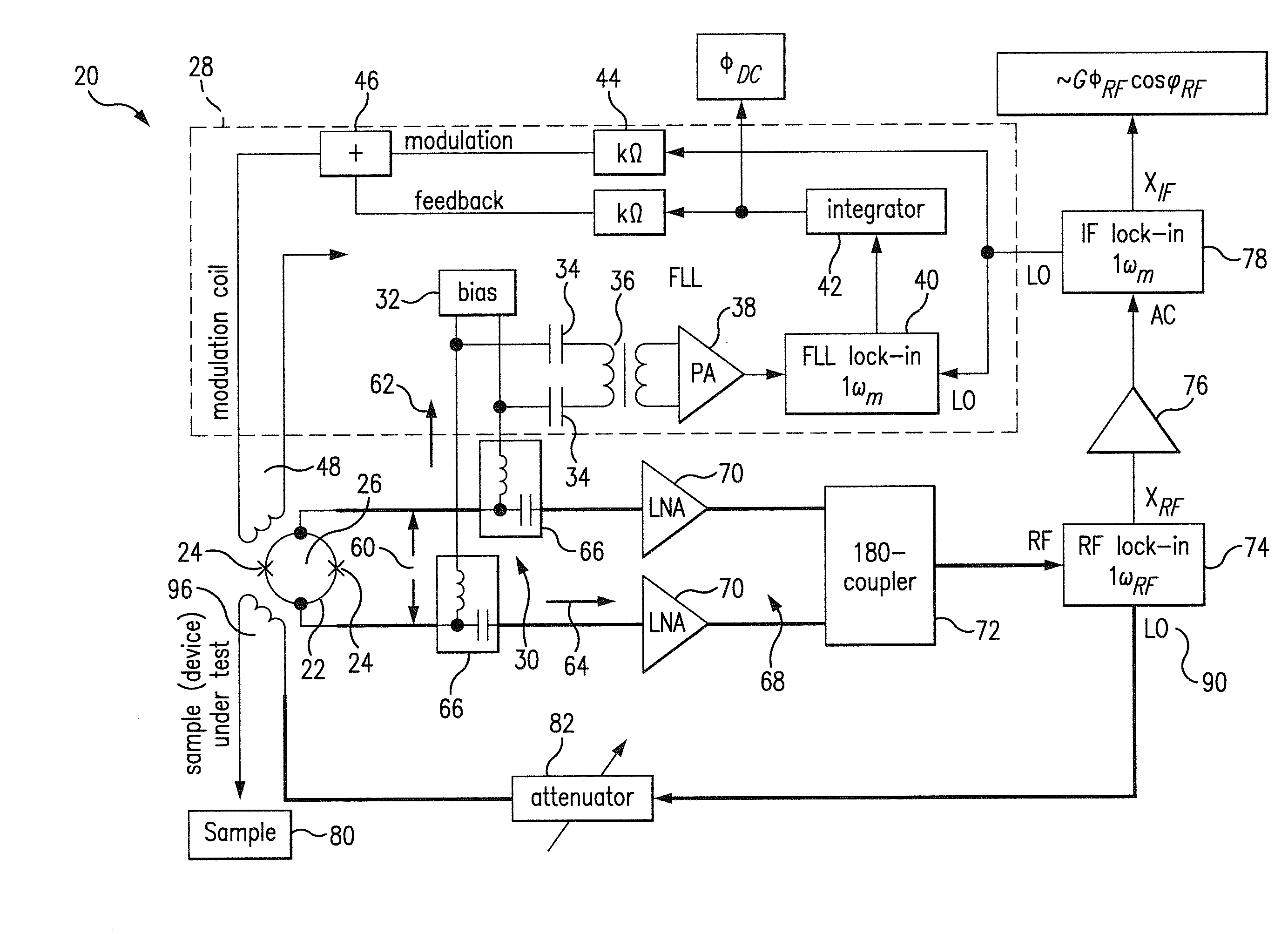
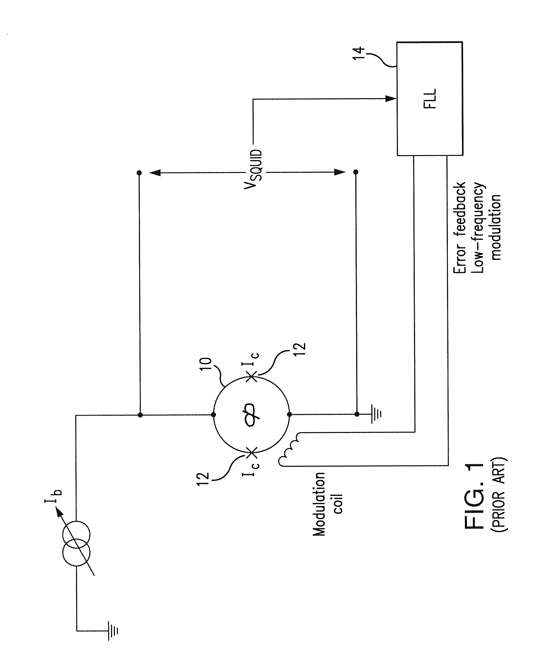
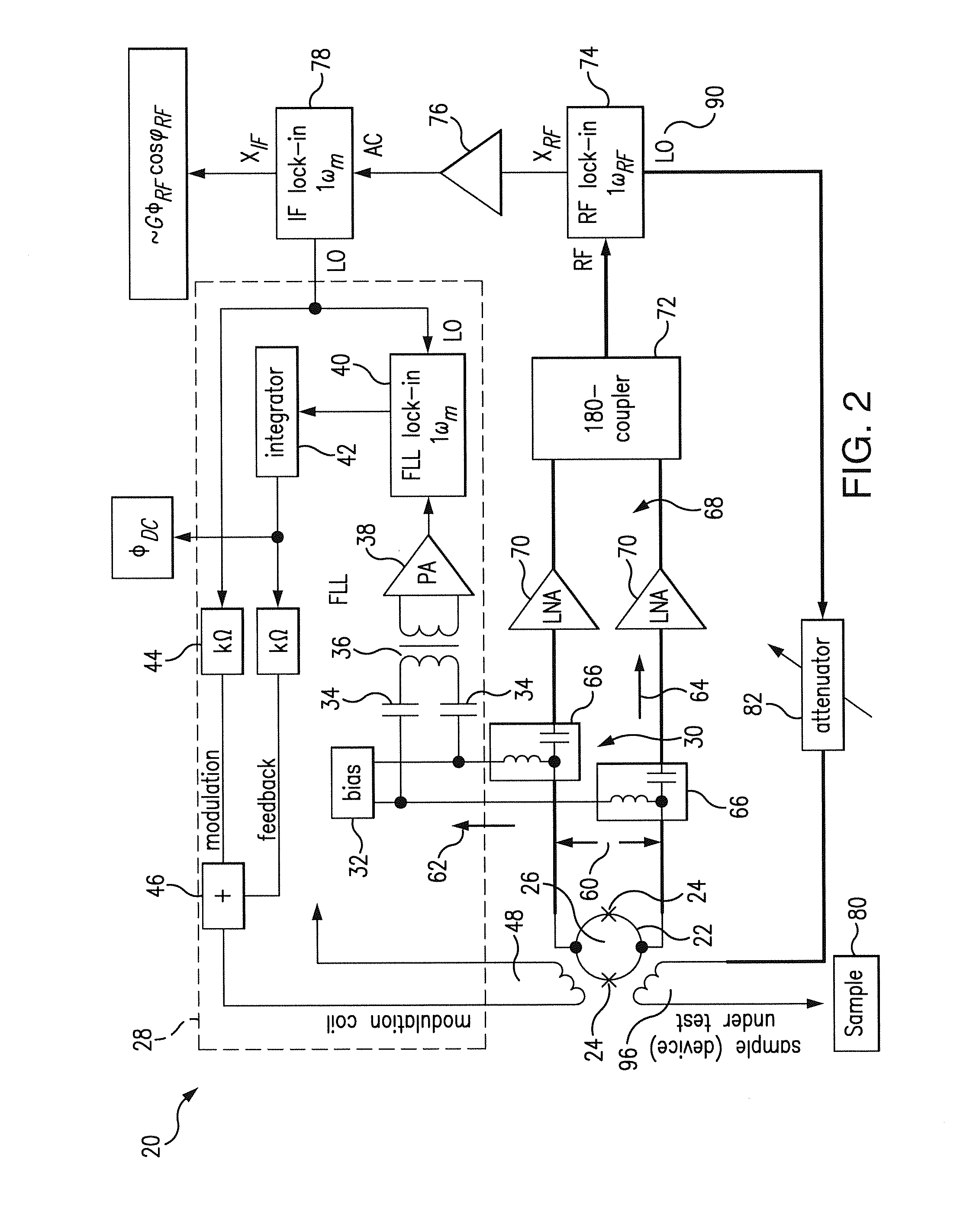
[0050]The ultimate goal of the present invention is to employ DC SQUID to create an output signal (IF signal, to be discussed in details in further paragraphs) that is a measure of RF magnetic field emanating from a sample of interest. Since the SQUID intrinsic bandwidth maybe as high as hundreds of GHz, the SQUID itself is not presenting a limiting factor. But the RF field oscillates at frequency which falls outside the FLL (flux-locked loop) bandwidth, i.e. higher than 20 MHz. For this reason, the flux-locked loop typically used in conjunction with DC SQUIDs will not respond to the measured RF field.

[0051]In order to overcome the FLL bandwidth limitation, the low frequency FLL is provided with the function of simultaneously locking the static flux for the DC SQUID as well as creating the AC bias for the RF flux at the maximum slope of the V-Φ function of the DC SQUID.

[0052]In the subject magnetometer, the RF flux emanating from the sample under study is superimposed on top of the ...


PUM


Abstract

An RF DC SQUID based magnetometer capable of sensing coherent magnetic fields up to 200 MHz and higher is developed which overcomes frequency limitations associated with noise signals due to transmission line delays between the SQUID circuit and readout electronics. The bandwidth limitations are overcome by superimposing the RF flux on the modulation flux to produce at the SQUID output a binary phase modulated RF voltage, which is processed to lock the static flux, and to control modulation regime by producing an AC bias for the RF flux. RF readout electronics based on a double lock-in technique (sequential demodulation of the RF SQUID voltage at the modulation flux frequency ωm and the RF flux frequency ωRF), yields a signal proportional to the product of amplitude and phase cosine of RF flux with linear dynamic range up to five orders in magnitude if compared to DC SQUID operated in traditional flux-locked loop regime.

Description

[0001]The work was funded by the NSF-SBIR contract Number IIP-0924610. The United States Government has certain rights to the Invention.FIELD OF THE INVENTION[0002]The present invention is directed to magnetic measurements, and specifically to magnetic measurements which are carried out with a Superconducting Quantum Interference Device (SQUID) magnetometer.[0003]Further, the present invention is directed to a DC SQUID based RF (radio frequency) magnetometer capable of sensing coherent magnetic fields in a diapason of 200 MHz and higher.[0004]The present invention is further directed to a DC SQUID magnetometer with 200 MHz (and higher) bandwidths in which an RF flux emanating from a sample under study is superimposed on the modulation flux to produce a binary phase modulated RF voltage at the SQUID output which is demodulated with the use of a double lock-in technique (at the frequency ωm of the modulation flux and at the frequency ωRF of the RF flux) to produce an output signal whi...

Claims


Application Information

Patent Timeline
Patent Type & Authority Applications(United States)
IPC IPC(8): G01R33/035
CPCG01R33/0356G01R33/035
Inventor OROZCO, ANTONIOTALANOV, VLADIMIR V.CAWTHORNE, III, ALFRED BENJAMINLETTSOME, JR., NESCO MARIO
Owner NEOCERA
Why Eureka
Try Eureka