Apparatus for transmitting image data

a technology of image data and apparatus, applied in the field of apparatus for transmitting image data, can solve the problems of usb-type interface unit, limited frame size, limited use of camlink or hdmi, etc., and achieve the effects of overcoming usb-type bandwidth limitation, simplifying the system, and increasing transmission efficiency

Active Publication Date: 2014-09-25
LG INNOTEK CO LTD
View PDF7 Cites 7 Cited by
  • Summary
  • Abstract
  • Description
  • Claims
  • Application Information

AI Technical Summary

Benefits of technology

[0026]One advantageous effect is that a standard type such as JPEG or H.264 is used to perform a standard image compression to increase transmission efficiency and to overcome a bandwidth limitation of USB type.
[0027]Another advantageous effect is that two endpoints of USB interface unit are used to transmit two images (depth image and color image) to a host system via each endpoint, whereby separate encoding and decoding are not required to simplify the system.
[0028]Still another advantageous effect is that a standard UVC is used to transmit image data, whereby the host system needs no separate device driver, and the host system processes the image data in response to API relative to the UVC, whereby additional API is not required to simplify the system.
[0029]Still further advantageous effect is that a camera can be easily used free from installation of additional software.

Problems solved by technology

The CAMLINK or HDMI is limited in use due to high price, such that an USB type interface is generally used except for handheld devices.
However, the USB-type interface unit (120) suffers from a disadvantage in that frame size is restricted due to bandwidth limitation (480 Mbps) in transmitting a depth image and a color image.
Furthermore, the USB-type interface unit (120) suffers from a disadvantage in that the host system (200) tends to be complicated, because one endpoint is used for transmitting an image data (see FIG. 1), a non-standard encoder (not shown) is required for transmitting two image data through one transmission path, and the host system (200) requires a non-standard decoder (not shown) for decoding the coded image data.
Meanwhile, the host system (200) also suffers from disadvantages in that it must be mounted with separate non-standard driver software for recognizing devices and a separate non-standard API (Application Programming Interface) to go with the separate non-standard driver software.

Method used


Image

  • Apparatus for transmitting image data
  • Apparatus for transmitting image data

Examples


Embodiment Construction

[0036]The following description is not intended to limit the invention to the form disclosed herein. Consequently, variations and modifications commensurate with the following teachings, and skill and knowledge of the relevant art are within the scope of the present invention. The embodiments described herein are further intended to explain modes known of practicing the invention and to enable others skilled in the art to utilize the invention in such, or other embodiments and with various modifications required by the particular application(s) or use(s) of the present invention.

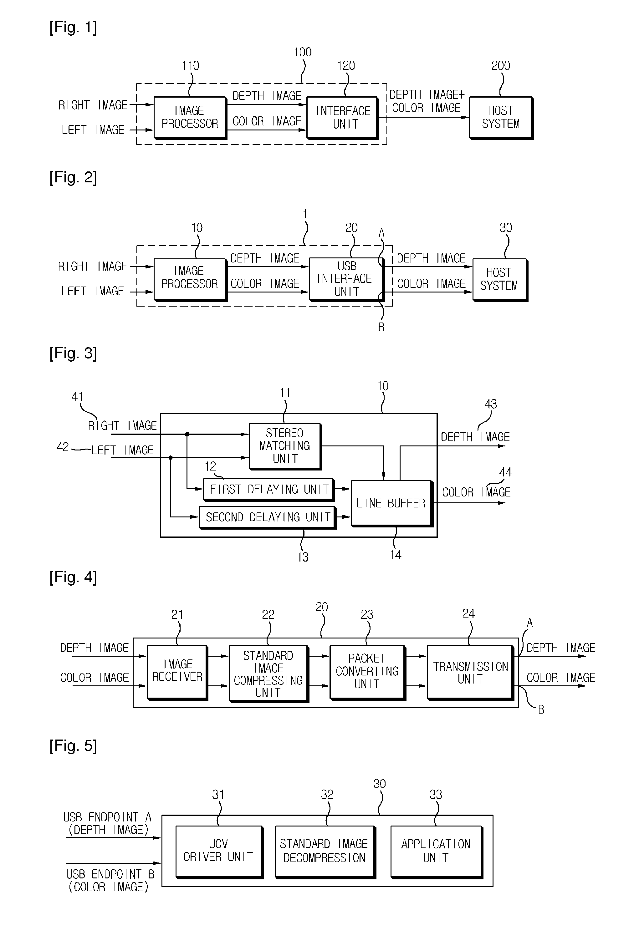
[0037]The disclosed embodiments and advantages thereof are best understood by referring to FIGS. 1-5 of the drawings, like numerals being used for like and corresponding parts of the various drawings. Other features and advantages of the disclosed embodiments will be or will become apparent to one of ordinary skill in the art upon examination of the following figures and detailed description. It is intended ...


PUM


Abstract

An image data transmitting apparatus is disclosed, the apparatus being configured to receive a right image and a left image and transmit the received right image and left image to a host system using a USB method, such that a depth image and a color image can be compressed in real time by a standard protocol, the compressed depth image and the color image are respectively converted to USB packet data, and the converted depth image and the color image are transmitted to a host system.

Description

TECHNICAL FIELD[0001]The teachings in accordance with exemplary embodiments of this invention relate generally to an apparatus for transmitting image data (hereinafter referred to as “image data transmission apparatus”, or simply “apparatus”).BACKGROUND ART[0002]Generally, a camera system outputting a depth image using a stereo camera transmits two image data of depth image and color image to a host system. FIG. 1 is a configurative block diagram illustrating an image data transmitting apparatus according to prior art.[0003]Referring to FIG. 1, a conventional image data transmitting apparatus (100) is configured such that a right image of M×N and a left image of M×N are image-processed by an image processor (110) to output a depth image of M×N and a color image of M×N, where frame size and synchronization of the depth image and color image are corrected by an interface (120), which is simultaneously outputted to a host system (200) such as a television or a computer (PC).[0004]In th...

Claims


Application Information

Patent Timeline
Patent Type & Authority Applications(United States)
IPC IPC(8): H04N19/88
CPCH04N19/00927H04N13/194H04N19/597H04N19/88H04N2213/003
Inventor YUN, JI HYUN
Owner LG INNOTEK CO LTD
Why Eureka
Try Eureka