Sensing sensor and sensing device using piezoelectric resonator

Inactive Publication Date: 2014-09-11
NIHON DEMPA KOGYO CO LTD
View PDF3 Cites 11 Cited by
  • Summary
  • Abstract
  • Description
  • Claims
  • Application Information

AI Technical Summary

Benefits of technology

The present patent includes improvements for a crystal unit used in a sensing sensor. The crystal unit has two electrodes for reference and detection at the back surface side. The front surface side also has a common electrode that is shared between the two reference electrodes. The left and right edges of a supply channel for sample solution are positioned on the region covered with the common electrode. This design ensures that the regions of the electrodes and the crystal region are not aligned widthwise of the supply channel, which avoids any difference in the ease of flow of the sample solution. As a result, the sample solution flows through the entire region of the channel, achieving stable measurement even with a low channel height.

Problems solved by technology

First, the QCM sensor used is constituted of two gold electrodes. Configuring one of the electrodes as a reference ensures differential measurement. However, since the thickness of the gold electrodes is 400 nm, in the case where hydrophobicity of the surfaces of the two electrodes is high when the sample solution is added from the inlet, the sample solution avoids the gold electrodes and exits from the outlet trickling the surrounding crystal. If a hydrophilic adsorbing layer for adsorbing the object to be sensed is disposed only at an electrode for detection among the two electrodes, hydrophilicity differs between each of the electrodes. In that case, the sample solution does not flow to the electrode of lower hydrophilicity, which may cause failure of measurement. These problems do not occur only if the thickness of the gold electrodes is thinned to 100 nm. However, there is a problem of deterioration of sensor characteristics when the thickness of the gold electrode is below 100 nm.

Method used


Image

  • Sensing sensor and sensing device using piezoelectric resonator
  • Sensing sensor and sensing device using piezoelectric resonator
  • Sensing sensor and sensing device using piezoelectric resonator

Examples


working example

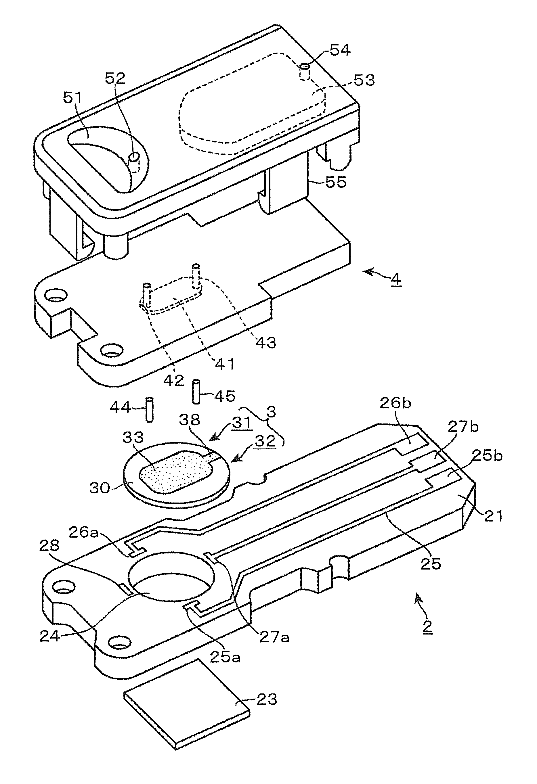
[0054]Data for confirming an effect in the case where the height of the channel of the sensing sensor 1 is narrowed and the capacity of the supply channel 40 is reduced is shown. The following working example was conducted. The common electrode 33 was disposed at the front surface side of the crystal unit 3 so as to cover the entire bottom surface of the supply channel 40. With the channel height of 50 μm, C-reactive protein with a concentration of 10 ng / ml was detected. As a comparative example, the measurement was performed with the sensing sensor similarly configured with the working example except that the channel height was set to 300 μm. Table 1 shows values of F1-F2 output in each sensing sensor according to the working example and the comparative example.

TABLE 1Channel Capacity (μm)F1-F2 (Hz)Working Example0.836.04Comparative Example5.002.13

[0055]As illustrated in Table 1, with the sensing sensor of the comparative example, F1-F2 was detected as 2.13 Hz. Meanwhile, with the ...


PUM


Abstract

A sensing sensor includes a crystal element having a first excitation electrode, a second excitation electrode, and a common electrode, an adsorbing layer, a wiring board, and a channel forming member. The crystal element is secured to the wiring board so as to form a space at one surface side of the first vibrating region and the second vibrating region. The channel forming member is disposed to form a supply channel of sample solution upward of each of the first vibrating region and the second vibrating region. The channel forming member is disposed such that an inferior surface of a left edge and a right edge of the channel forming member is positioned on the common electrode. The channel forming member is formed such that an injection port of the sample solution and a discharge port of the sample solution are opposed to the crystal element.

Description

CROSS-REFERENCE TO RELATED APPLICATION[0001]This application claims the priority benefit of Japanese application serial no. 2013-045396, filed on Mar. 7, 2013. The entirety of the above-mentioned patent applications is hereby incorporated by reference herein and made a part of specification.TECHNICAL FIELD[0002]The present disclosure relates to a technique to sense an object to be sensed using a piezoelectric resonator where a unique vibration frequency changes when the object to be sensed is absorbed by an adsorbing layer disposed at a surface of the sensing sensor.DESCRIPTION OF THE RELATED ART[0003]For example, a sensing sensor utilizing Quartz Crystal Microbalance (QCM) as disclosed in Japanese Unexamined Patent Application No. 2009-206792 is shown as a method for sensing an object to be sensed in a sample fluid such as a trace amount of protein in blood or serum. The QCM uses a crystal unit with an adsorbing layer that adsorbs the object to be sensed to a surface of an excitati...

Claims


Application Information

Patent Timeline
IPC IPC(8): G01N29/02
CPCG01N29/022G01N2291/02466G01N33/48707
Inventor SHINOBU, WAKAKOKUKITA, HIROYUKIWAKAMATSU, SHUNICHI
Owner NIHON DEMPA KOGYO CO LTD
Why Eureka
Try Eureka