
Method and apparatus for measuring brightness

Inactive Publication Date: 2006-06-01
ASIA OPTICAL CO INC
View PDF5 Cites 8 Cited by
  • Summary
  • Abstract
  • Description
  • Claims
  • Application Information

AI Technical Summary

Benefits of technology

[0007] Accordingly, an object of the present invention is to provide an apparatus for measuring brightness to simplify the operation of measuring brightness and to improve the examining process and the measurement precision.
[0008] A further object of the present invention is to provide a method for precisely measuring brightness which is applied to any device having a light-emitting display unit and is used to stimulate the factual brightness of the light thereof arriving at the user's eyes, thereby precisely quantizing the measurement result.
[0009] Another object of the present invention is to provide a method and an apparatus for measuring brightness which is applied to a small-area of light-displaying unit to stimulate the focusing ability of the user's eyes, thereby making for more conveniently measuring brightness and also fast improving the examining process and the measurement precision.

Problems solved by technology

Otherwise, if the factual brightness value is estimated directly by the eyes of user, it is inconsistent and imprecise because of a difference caused by users' sense of sight.
However, it is very difficult to measure the factual brightness value of the LED or the OLED in the laser telescope using these prior apparatuses, because an area of the light projected by the LED or the OLED is very small.
Additionally, these apparatuses are very expensive and not fit to be utilized in a scene of mass production.

Method used


Image

  • Method and apparatus for measuring brightness
  • Method and apparatus for measuring brightness
  • Method and apparatus for measuring brightness

Examples


Embodiment Construction

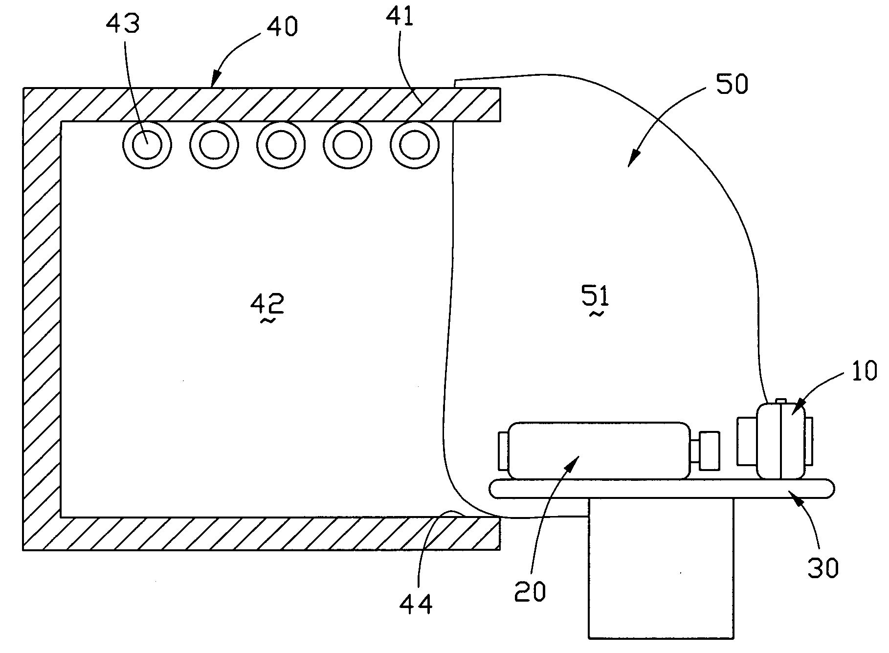
[0038] In this preferred embodiment of the present invention, we will take a binocular laser telescope as an example for illustrating a method and an apparatus for measuring brightness according to the present invention.

[0039] In the binocular laser telescope, the question described in the prior art is also existing. In other words, there is a difference between the factual brightness of the light, which is representing a reticle and a distance value observed by user, and the original brightness of an OLED because the lenses located in the binocular laser telescope can absorb and reflect the light emitted by the OLED. Therefore it's essential to do a double check for the factual brightness of the light of the OLED that can arrive at the eyes of user. Whereby the factual brightness of the product thus is confirmed whether or not according with standard. A method and an apparatus for measuring brightness according to the present invention is to measure and quantize the factual bright...


PUM


Abstract

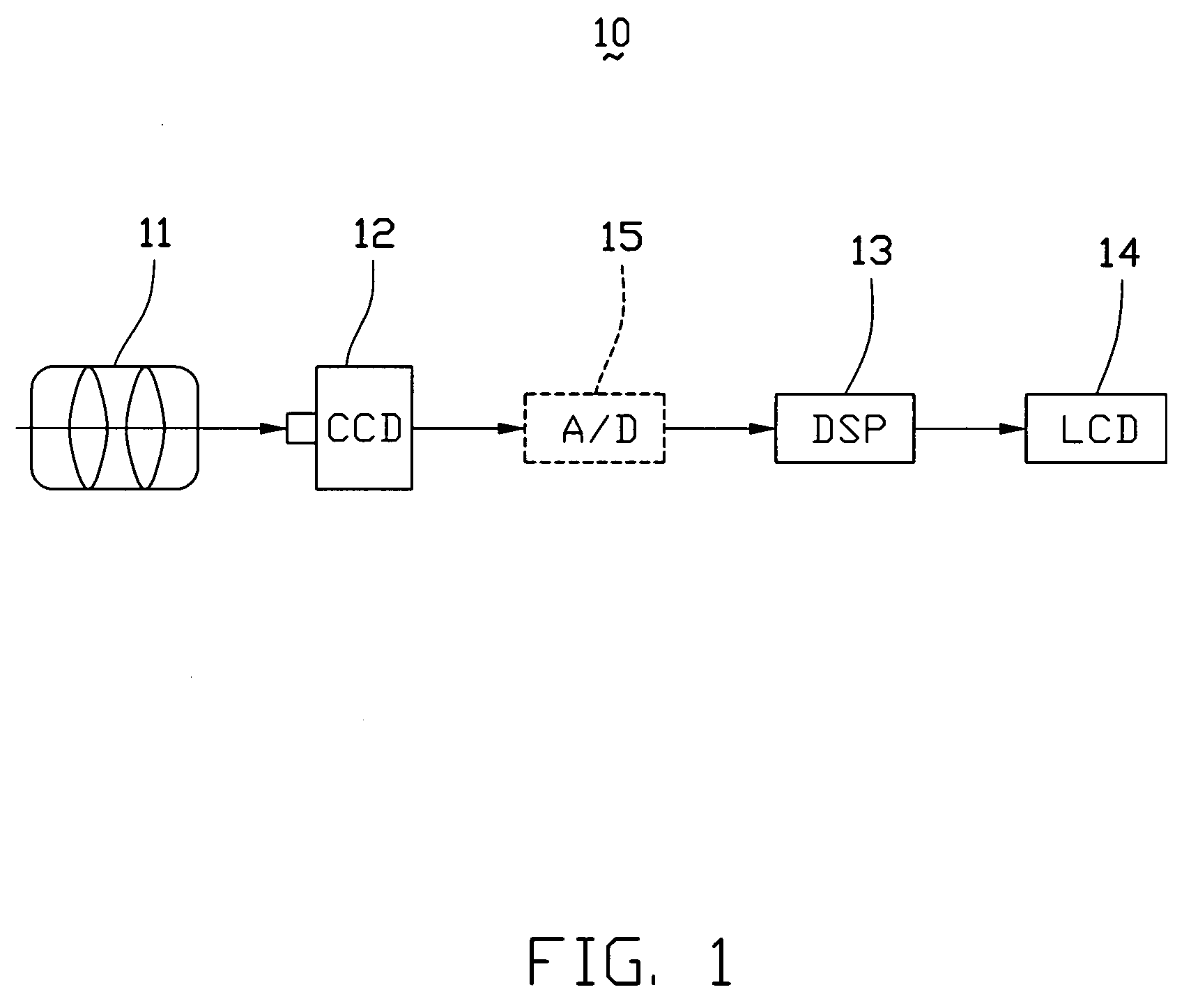
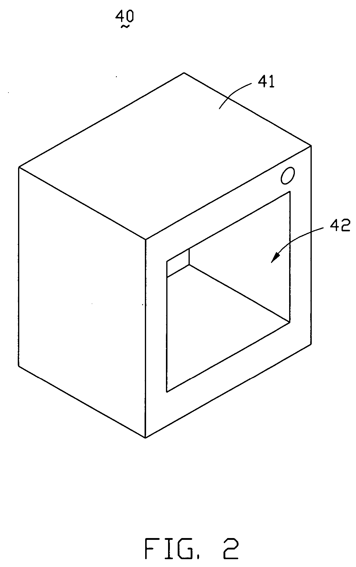
An apparatus for measuring brightness transmitted by a light-emitting display unit of a laser telescope and observed by the user's eyes comprises a focusing unit (11), a sensor unit (12), a processing unit (13) and a display unit (14). A method of measuring brightness includes the steps of: providing a constant color temperature to simulate the external light; providing a tool platform and locating the apparatus for measuring brightness and the laser telescope under test thereon; further providing a light-impermeable cover to cover the laser telescope and the apparatus for avoiding the external light interfering with the measurement of brightness; then turning on the laser telescope and enabling it to range; picking up the light of a reticle and a measured value transmitted from the light-emitting display unit by means of the apparatus for measuring brightness; and at last, displaying the measured value on the display unit of said apparatus for measuring brightness.

Description

BACKGROUND OF THE INVENTION [0001] 1. Field of the Invention [0002] The present invention relates to an apparatus for measuring brightness, and more particularly relates to a method and an apparatus for precisely measuring the brightness of a device having a light-emitting display unit. [0003] 2. Description of the Prior Art [0004] A light emitting diode (LED) or an organic light emitting diode (OLED) located in a laser telescope is used to display a reticle and a distance value between a target object and the laser telescope. Generally, an original brightness value of the LED or the OLED is offered by manufactory, but it isn't always precise. In the laser telescope, the light of said reticle and the distance value which are displayed on LED or OLED needs to pass through several lenses, for example a focusing lens, a prism group and a ocular lens etc., and then they are observed by user. The factual brightness of the light entering the eyes of user will decline because the lenses of...

Claims


Application Information

Patent Timeline
IPC IPC(8): G01J1/42
CPCG01J1/32G01J1/42G01J2001/4247
Inventor WANG, CHUNG-WEIYANG, SHIH-HSIEN
Owner ASIA OPTICAL CO INC
Learn More