Non-pneumatic tire

a technology of non-pneumatic tires and tires, which is applied in the direction of tires, high-resiliency wheels, vehicle components, etc., can solve the problem of unavoidable puncture, and achieve the effect of keeping the puncture rate constant and easy assembly

Inactive Publication Date: 2014-09-11
BRIDGESTONE CORP
View PDF16 Cites 50 Cited by
  • Summary
  • Abstract
  • Description
  • Claims
  • Application Information

AI Technical Summary

Benefits of technology

[0008]According to the present invention, it is possible to obtain a non-pne

Problems solved by technology

In recent years, in conventional pneumatic tires that are used after the interior thereof has been filled with

Method used


Image

  • Non-pneumatic tire
  • Non-pneumatic tire
  • Non-pneumatic tire

Examples


Embodiment Construction

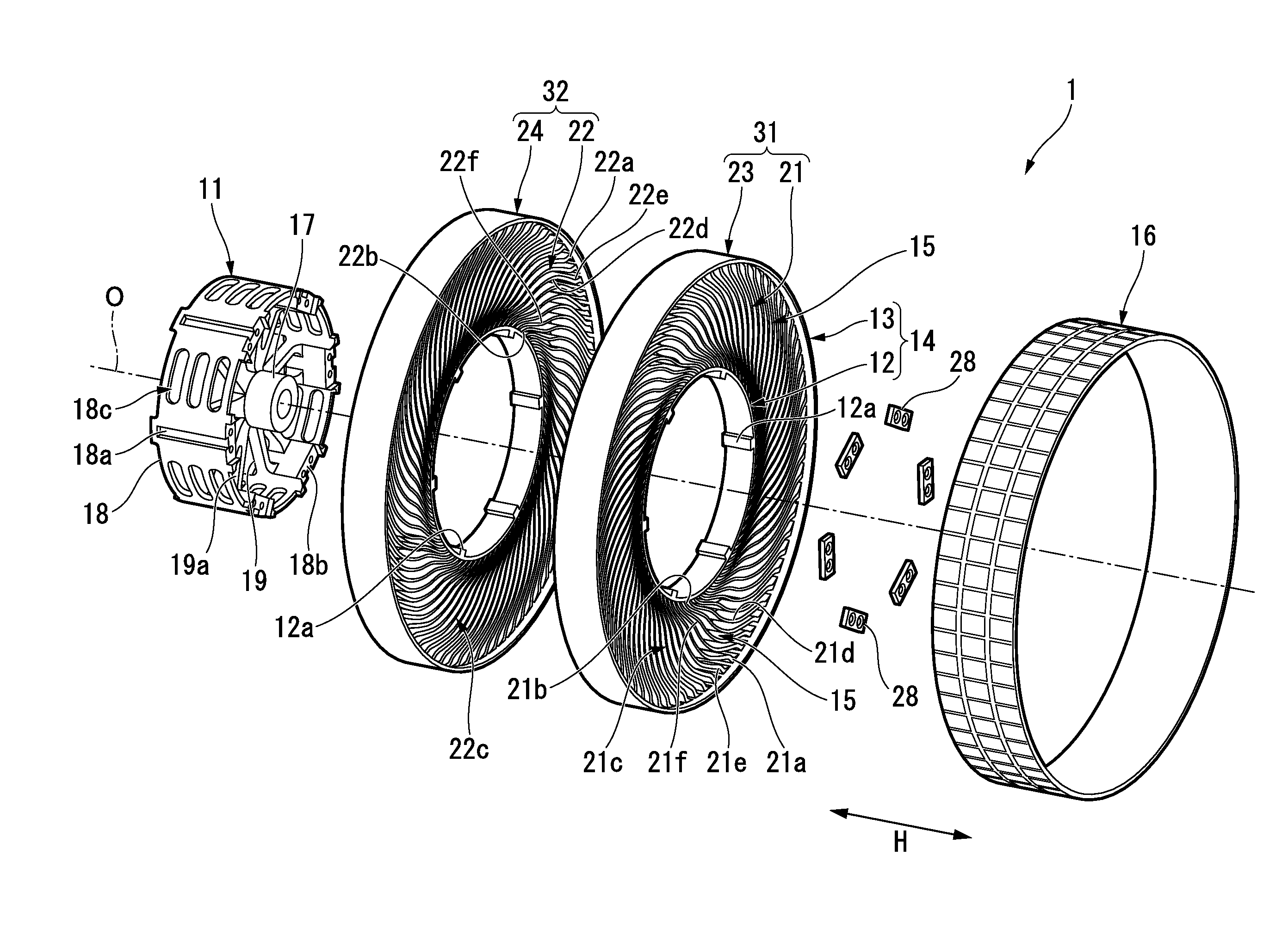
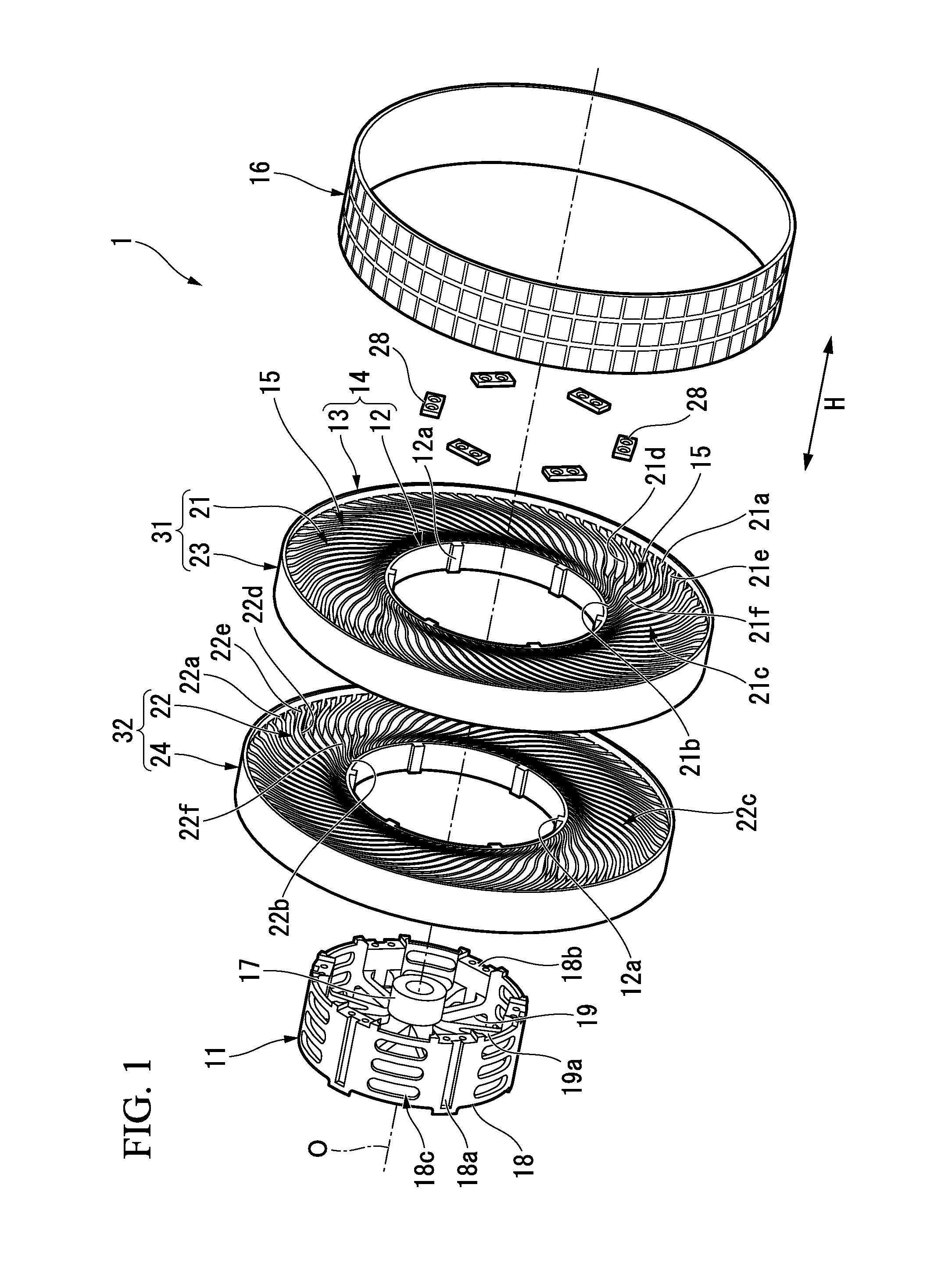
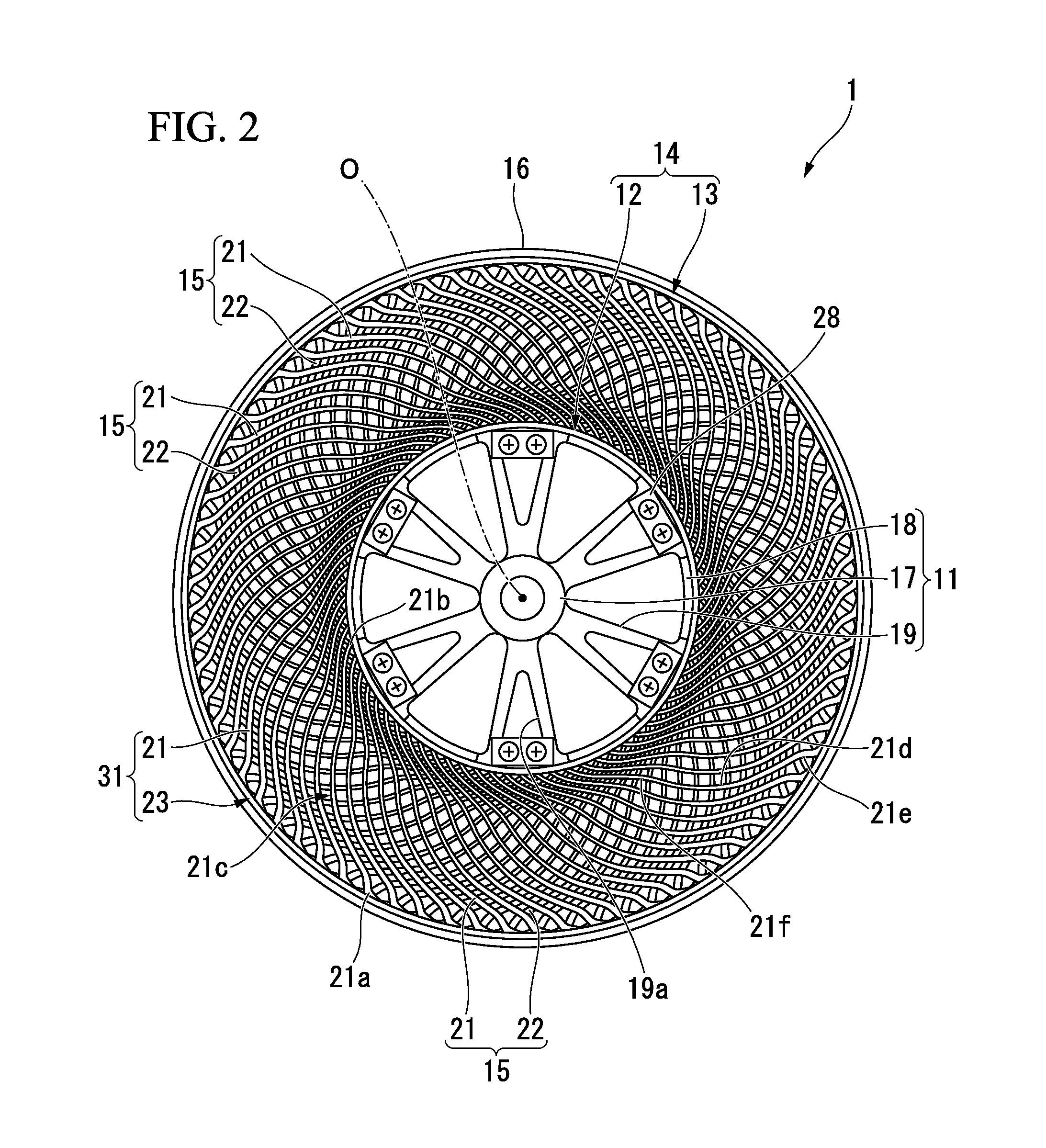
[0013]Hereinafter, an embodiment of a non-pneumatic tire of the present invention will be described with reference made to FIG. 1 through FIG. 4.

[0014]A non-pneumatic tire 1 is provided with a mounting body 11 that is mounted on a vehicle axle (not shown), and a ring component 14 that has an inner cylindrical body 12 that is fitted onto the outside of the mounting body 11 and an outer cylindrical body 13 that encircles the inner cylindrical body 12 from the outside in the tire radial direction. In addition, the non-pneumatic tire 1 is also provided with a plurality of linking components 15 that are lined up in the circumferential direction of the tire between the inner cylindrical body 12 and the outer cylindrical body 13, and that link the two cylindrical bodies 12 and 13 together such that they can be freely elastically displaced relatively to each other, and with a tread component 16 that is provided so as to extend around the entire outer circumferential surface of the outer cyl...


PUM


Abstract

A non-pneumatic tire is provided with: a mounting body (11) that is mounted on a vehicle axle; a ring component (14) that is provided with an inner cylindrical body (12) that is fitted onto the outside of the mounting body (11), and an outer cylindrical body (13) that encircles the inner cylindrical body (12) from the outside in the radial direction of the tire; and a plurality of linking components (15) that are lined up along the circumferential direction of the tire between the inner cylindrical body (12) and the outer cylindrical body (13), and that link together these two cylindrical bodies (12, 13) such that they can be elastically displaced relative to each other, wherein the ring component (14) and the plurality of linking components (15) are formed integrally as a single unit.

Description

TECHNICAL FIELD[0001]The present invention relates to a non-pneumatic tire that does not need to be filled with compressed air when being used. Priority is claimed on Japanese Patent Application No. 2011-230680, filed Oct. 20, 2011, the contents of which are incorporated herein by reference.BACKGROUND ART[0002]In recent years, in conventional pneumatic tires that are used after the interior thereof has been filled with compressed air, considering the structure of such tires, the occurrence of punctures is an unavoidable problem.[0003]In order to solve this problem, a non-pneumatic tire such as that disclosed, for example, in Patent document 1 (see below) that is provided with a mounting body that is mounted on a vehicle axle, a ring-shaped body that encircles the mounting body from the outside in the radial direction of the tire, and a plurality of linking components that are lined up in the circumferential direction of the tire between the mounting body and the ring-shaped body has...

Claims


Application Information

Patent Timeline
IPC IPC(8): B60B9/04
CPCB60B9/04B60C7/14B60C7/22B60C7/146
Inventor ABE, AKIHIKONISHIDA, MASASHI
Owner BRIDGESTONE CORP
Why Eureka
Try Eureka