Electrical power transmission system and method

Active Publication Date: 2014-09-11
PICHKUR YAROSLAV ANDREYEVICH
View PDF4 Cites 3 Cited by
  • Summary
  • Abstract
  • Description
  • Claims
  • Application Information

AI Technical Summary

Benefits of technology

[0008]According to another aspect of the invention, a power carrier for transmitting an electrical current comprises a proximal end having first and second proximal electrical connections leading to it. A distal end is opposite the proximal end and has first and second distal electrical connections leading from it. A first set of electrical conductors are all electrically connected in parallel between the first proximal electrical connection and the first distal electrical connection, and a second set of electrical conductors are all electrically connected in parallel between the second proximal electrical connection and the second distal electrical connection. The electrical conductors extend over a length of the carrier and each is surrounded by insulating material so as to be electrically separate from each other over the length in a cross-sectional arrangement relative to one another in the carrier. The cross-sectional area remains constant over the length of the carrier. The first se

Problems solved by technology

In many environments, magnetic fields of this type are undesirable,such as under high-power transmission lines or in power cords in certain locations, or generally any area where people or animals are exposed to high magnetic fields.
For example, power supplies for pacemakers implanted in a person's body transmit power inside the person's body, and a magnetic field there is undesirable.
As another example, in the context of hybrid cars, power is supplied via cables within the body of the car, usually as relativel

Method used


Image

  • Electrical power transmission system and method
  • Electrical power transmission system and method
  • Electrical power transmission system and method

Examples


example

[0056]An experiment was conducted to determine the efficacy of a carrier according to an embodiment of the invention.

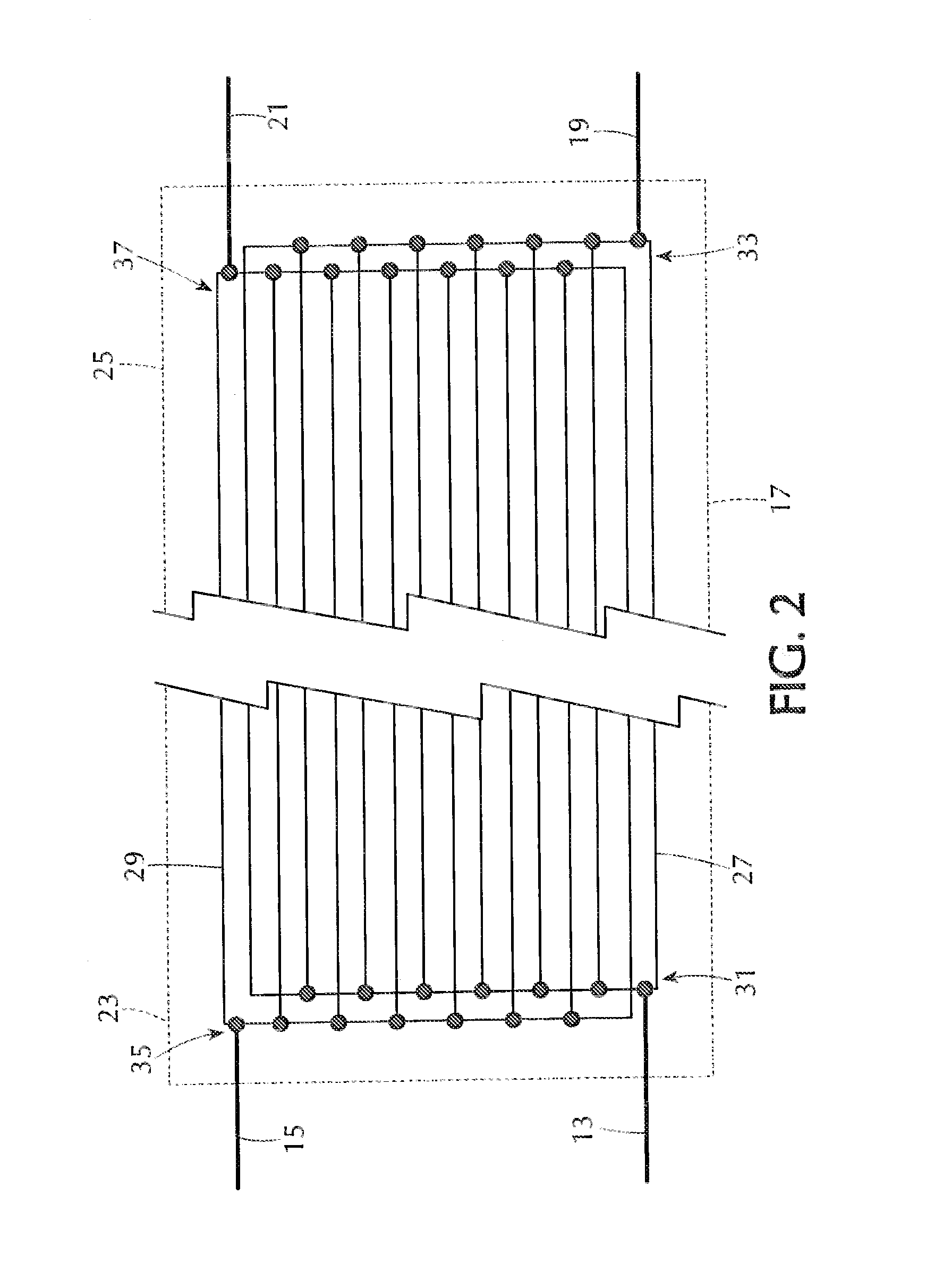
[0057]For the experiment, the carrier used was of a cross section as seen in FIG. 11. The carrier 145 was formed as a matrix of wires 147 and 149, all of which were 28 AWG stranded wire. The wires 147 and 149 were supported in a matrix arrangement as shown, where the wires were spaced 0.05″ apart in the rows and the columns. Wires 147 were all connected in parallel and wires 149 were all connected in parallel as in the schematic of FIG. 2. The insulation referenced generally as 151 around the wires 147 and 149 was 300 volt gray PVC insulation.

[0058]As a control example, a typical two wire electrical cord was used.

[0059]A 120 volt AC power source was connected at one end of the two-wire electrical cord, and a 950 watt power load was connected at the other end. The magnetic field around the two-wire cord was then measured, yielding a reading of 72 milliGauss.

[0060]The s...


PUM


Abstract

A power carrier transmits an electrical current to and from a load. The carrier has a set of wires carrying electricity in parallel to the load and another set of wires carrying the electricity back in parallel from the load. The wires are organized with equal numbers of wires form each set grouped around a junction alternatingly, so that as a result the magnetic fields created by the electricity flowing through the two sets of wires cancel each other out in the junction. The carrier may have several junctions in a rectangular matrix pattern or hexagonal close-packed pattern, or other patterns, e.g., octagonal, which may be combined with junctions with different numbers of wires. The resulting power carrier has a reduced external magnetic field.

Description

FIELD OF THE INVENTION[0001]This invention relates to systems for transmitting power, and more particularly to transmitting power with reduced magnetic field effects outside the conductor.BACKGROUND OF THE INVENTION[0002]The use of conducting wires to carry electrical power is well known, as is the fact that a current passing through a conductor generates an external magnetic field around the conductor.[0003]In many environments, magnetic fields of this type are undesirable,such as under high-power transmission lines or in power cords in certain locations, or generally any area where people or animals are exposed to high magnetic fields. For example, power supplies for pacemakers implanted in a person's body transmit power inside the person's body, and a magnetic field there is undesirable. As another example, in the context of hybrid cars, power is supplied via cables within the body of the car, usually as relatively high-amperage, high-voltage alternating current, e.g., 360 volt A...

Claims


Application Information

Patent Timeline
IPC IPC(8): H05K9/00H02G3/00
CPCH02G3/00H05K9/00H01F27/2828
Inventor PICHKUR, YAROSLAV ANDREYEVICHTIAJOLOFF, ANDREW LLOYD
Owner PICHKUR YAROSLAV ANDREYEVICH
Why Eureka
Try Eureka