Variable speed drive for oblique feeding drums

a variable speed drive and feeding drum technology, applied in the field of variable speed drive for oblique feeding drums, can solve the problems of increasing the increasing the power requirement of the drive, and increasing the wear of the cutting knife and the braking arrangement of the header, so as to achieve the effect of constant rotational speed of the mower and the intake drive assembly

Active Publication Date: 2005-09-08
MASCHFAB KEMPER
View PDF8 Cites 1 Cited by
  • Summary
  • Abstract
  • Description
  • Claims
  • Application Information

AI Technical Summary

Benefits of technology

[0012] Preferably, the mower and intake drive assembly is driven by a completely mechanical drive-line from an internal combustion engine used as the main drive power of the forage harvester, that is, avoiding hydraulic drive components that are subject to power losses. Thereby, the result is a rotational speed of the mower and intake drive assembly that is proportional to the rotational speed of the internal combustion engine. Since the latter is usually constant, the rotational speed of the mower and intake drive assembly also remains constant.

Problems solved by technology

The disadvantage in a variation of the rotational speeds of all driven elements of the header is seen in the fact that the rotational speeds of the mower and intake drive assemblies are also increased, although that speed increase does not bring about any improvement in the conveying of the harvested crop and hence is not necessary.
It increases the power requirement of the drive and results in increased wear of the cutting knives and the braking arrangements of the header.
Here the disadvantage is seen in the fact that two drive connections must be provided between the forage harvester and the header, that is, between the slope conveyor drums and the first hydraulic motor as well as between the remaining driven elements of the header and the second hydraulic motor.
Thereby, the attachment and removal of the header to or from the forage harvester is rather time consuming.
Furthermore, the efficiency of the hydraulic rives is relatively poor.
Here, too, a number of hydraulic drives with limited efficiency are provided.

Method used


Image

  • Variable speed drive for oblique feeding drums
  • Variable speed drive for oblique feeding drums
  • Variable speed drive for oblique feeding drums

Examples


Embodiment Construction

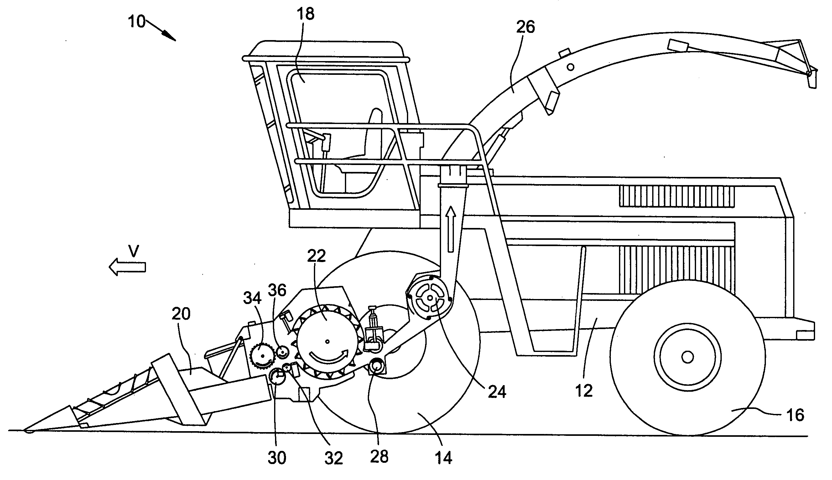
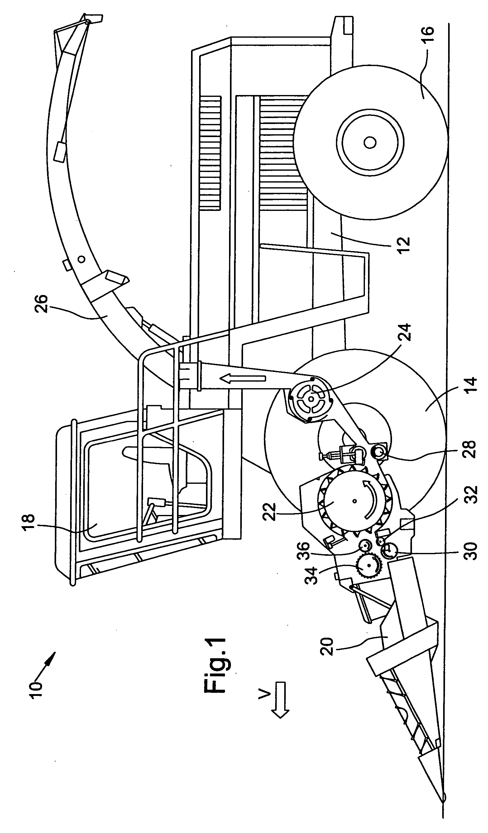
[0018] A self-propelled forage harvester 10, as shown in FIG. 1, is supported on a frame 12 that is carried by driven front wheels and steerable rear wheels 14 and 16. The forage harvester 10 is controlled from an operator's cab 18 from which a header 20 for mowing crops to be harvested can be viewed. Crop taken up from the ground by means of the header 20, for example, corn, grass or the like is conducted to a chopper drum 22 by lower rough pressing rolls 30, 32 and upper rough pressing rolls 34, 36 arranged in an intake channel of the harvesting machine 10. The chopper drum 22 chops the crop into small pieces and delivers it to a conveyor arrangement 24. As a rule, the upper rough pressing rolls 34, 36 are arranged so that they can move relative to the lower intake rolls 30,32 and are forced against the latter by spring force. The crop leaves the harvesting machine 10 to an accompanying trailer over a duct 26 mounted for being selectively rotated about an upright axis. A post chop...


PUM


Abstract

A forage harvester header is coupled to a forage harvester and is equipped with at least one mower and intake drive assembly for cutting crop and transporting the cut crop to a discharge conveyor which delivers the crop to a feed channel of the forage harvester. The drive arrangement for the header is such that the velocity of the discharge conveyor can be varied relative to the velocity of the mower and intake drive assembly.

Description

FIELD OF THE INVENTION [0001] The invention concerns a header attachable to a forage harvester for mowing crops to be harvested, which crops have having stalks, and with at least one mower and intake drive assembly for the mowing and transporting away of harvested crop and a discharge conveyer to which harvested crop can be conducted from the mower and intake drive assembly and that is arranged to conduct the crop to the intake channel of the forage harvester, where the speed of the discharge conveyor can be varied relative to the speed of the mower and intake drive assembly. BACKGROUND OF THE INVENTION [0002] Headers for mowing crops having stalks so as to be harvested are used in combination with self-propelled, towed or attached forage harvesters for the total plant harvest, for example, for the harvest of silage corn. A commonly used type of such a header is described in EP 0 760 200A. The header of this publication includes a number of mower and intake drive assemblies arranged...

Claims


Application Information

Patent Timeline
Patent Type & Authority Applications(United States)
IPC IPC(8): A01D43/08
CPCA01D69/00A01D43/081
Inventor WUBBELS, RICHARD
Owner MASCHFAB KEMPER
Why Eureka
Try Eureka