

Methods and systems for producing acetic acid
- Summary
- Abstract
- Description
- Claims
- Application Information
AI Technical Summary
Benefits of technology
Problems solved by technology
Method used
Image

Examples
example 1
f Dual Purpose Reactor Cooler
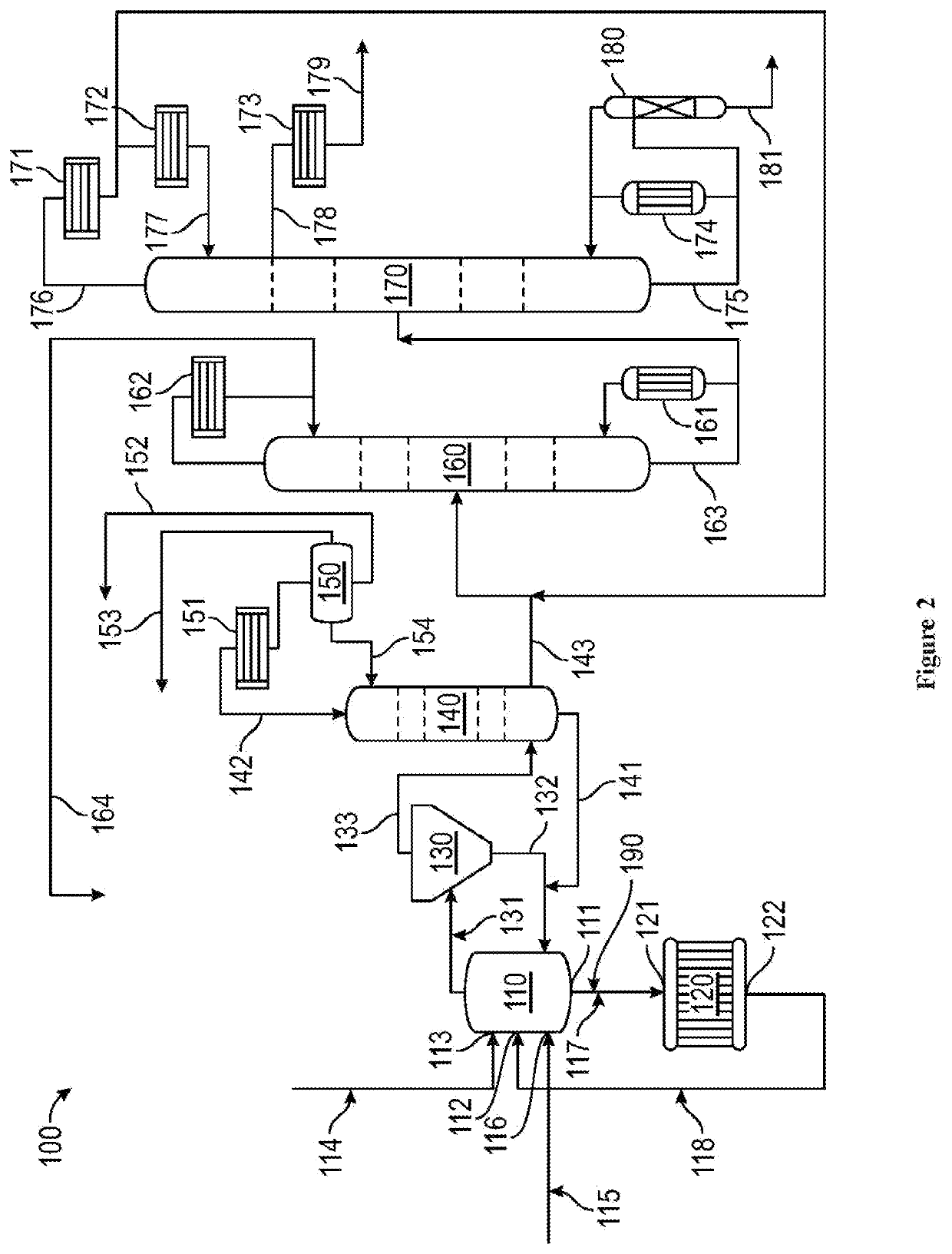
[0068]The GAA reactor system of FIG. 2 was used in this example. The reactor and reactor cooler operating parameters are summarized as Table 2.
[0069]The extent of continuing reaction (MeAc and CO consumption & GAA formation) in the reactor cooler was controlled by adjusting the reactor cooler temperature. The data of Table 2 indicated that the space time yield (STY) in the reactor cooler was approximately half of the reactor STY at the temperatures indicated at Table 2.
[0070]Based on reactor cooler inlet composition (substantially reactor composition), STY, and residence time, reactor cooler outlet compositions were analyzed, as depicted at Table 3. It should be noted that as MeAc was only partially consumed in the reactant cooler, iodide equilibrium was unaffected and the MeI / HI ratio remained relatively constant.
TABLE 2VariableReactorRx CoolerTemp, ° C.190.6179.4Approximate STY105Residence Time, mins.171.35Liquid Volume, liters56,781.25,212.5
TABLE 3Com...
example 2
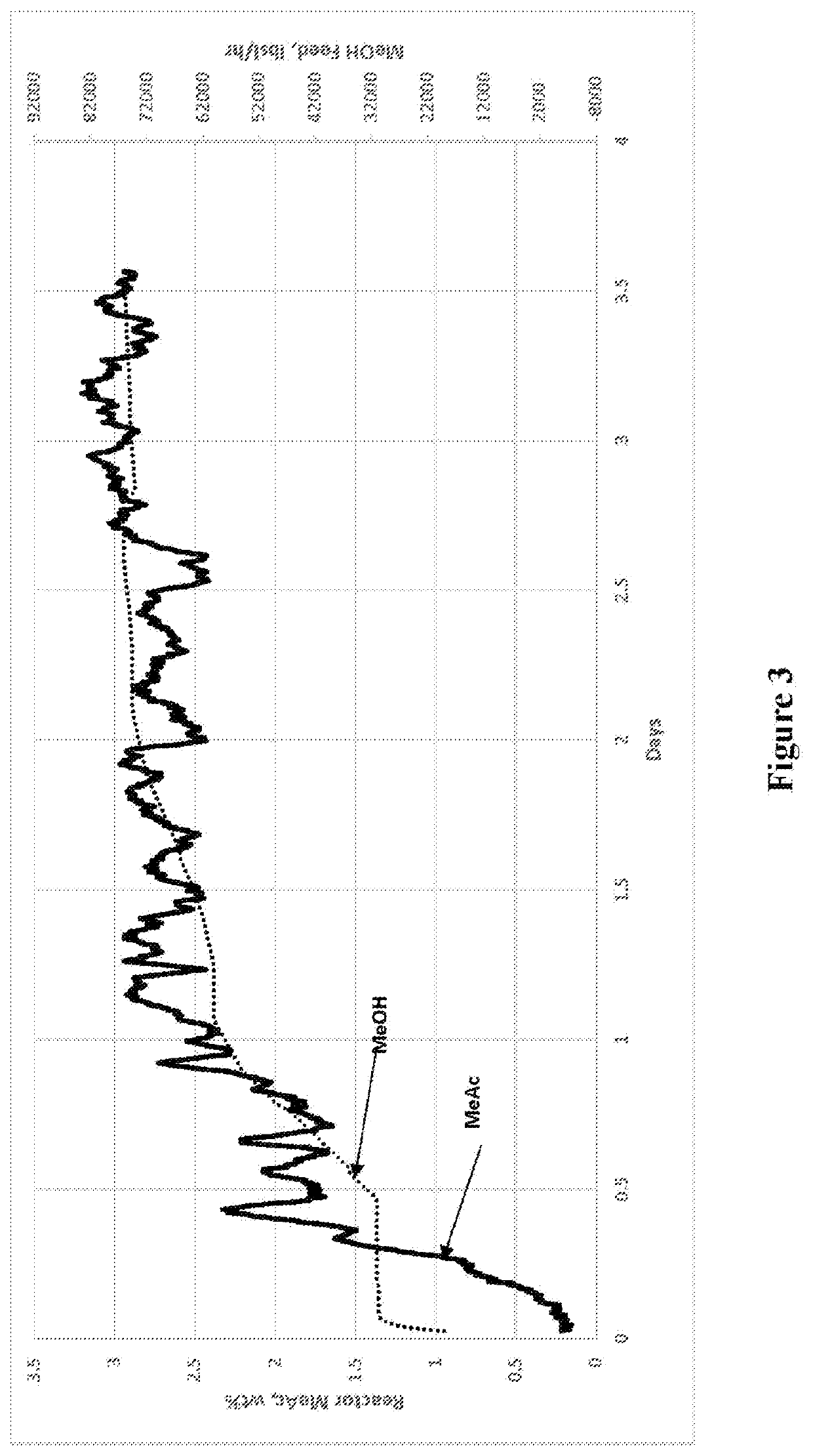
[0074]As described above, decreasing the feed rate can decrease methyl acetate concentration. By corollary, increasing the feed rate will increase methyl acetate concentration. FIG. 3 presents start-up data collected over a 3.5 day period of a continuous methanol carbonylation unit without reactor cooler in operation, e.g., using the system of Comparative Example 1. As shown, the target steady state MeAc concentration of about 3 wt % was obtained at the conclusion of the methanol feed ramp. In this case, the Rh catalyst concentration was increased to keep MeAc concentration at or below 3 wt %.
[0075]FIG. 4 represents a simulated condition where a similar steady state methyl acetate concentration is maintained but now at a favorably higher feed rate and, by corollary, higher production rate. This condition can be reached by an increase in Rh catalyst concentration, an increase in reactor temperature, an increase in methyl iodide promoter concentration or by bringing the reactor cooler...
PUM
| Property | Measurement | Unit |
|---|---|---|
| Temperature | aaaaa | aaaaa |
| Temperature | aaaaa | aaaaa |
| Temperature | aaaaa | aaaaa |
Abstract
Description
Claims
Application Information