LEAK DETECTION FORMULA, ANALYZER and METHODS OF USE

Active Publication Date: 2014-09-11
AUTOMOTIVE TEST SOLUTIONS
View PDF28 Cites 19 Cited by
  • Summary
  • Abstract
  • Description
  • Claims
  • Application Information

AI Technical Summary

Benefits of technology

[0014]The present invention allows fast, accurate leak testing to be done in the field, in varying lighting conditions (including poor lighting), where the ambient air is moving, and without the need for a smoke generating machine or the associated chemicals (including a fluorescent dye). Hole sizes as small as 0.001″ in diameter c

Problems solved by technology

While the detector can quickly and easily locate the general area (base location) of the leak, it may not be able to determine the exact location.
However, it has been determined that a large leak size, or sufficiently high pressure, or both, will allow enough gas to be released that the foam cannot hold the pressu

Method used


Image

  • LEAK DETECTION FORMULA, ANALYZER and METHODS OF USE
  • LEAK DETECTION FORMULA, ANALYZER and METHODS OF USE
  • LEAK DETECTION FORMULA, ANALYZER and METHODS OF USE

Examples


Example

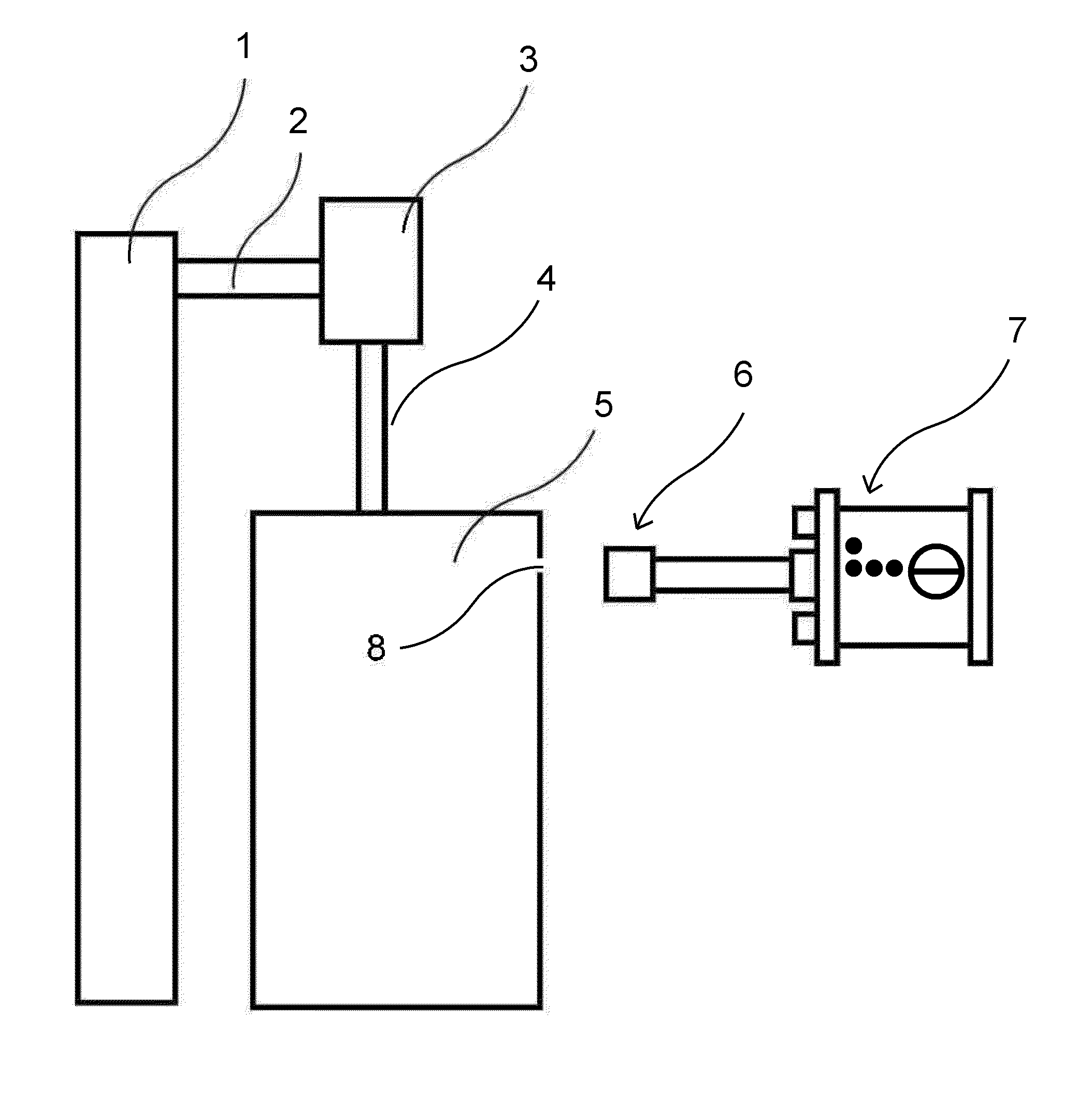
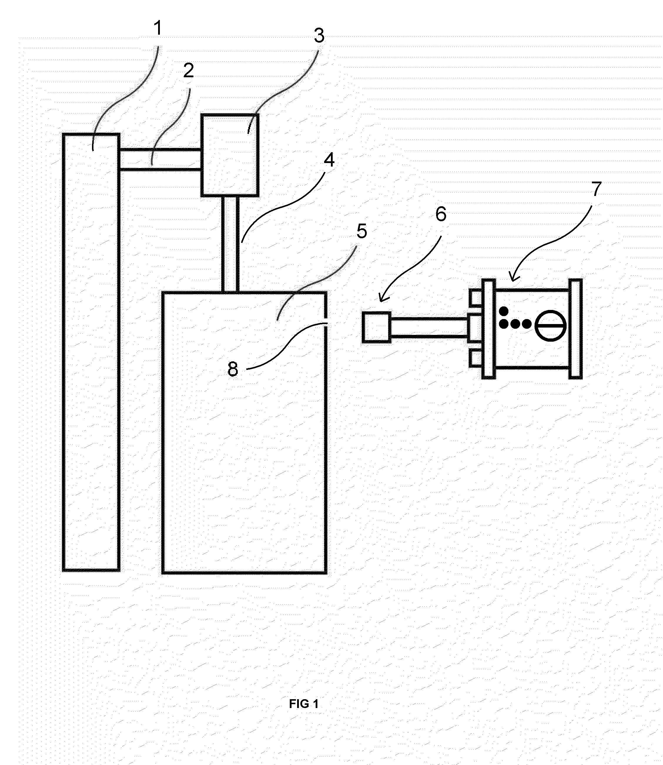
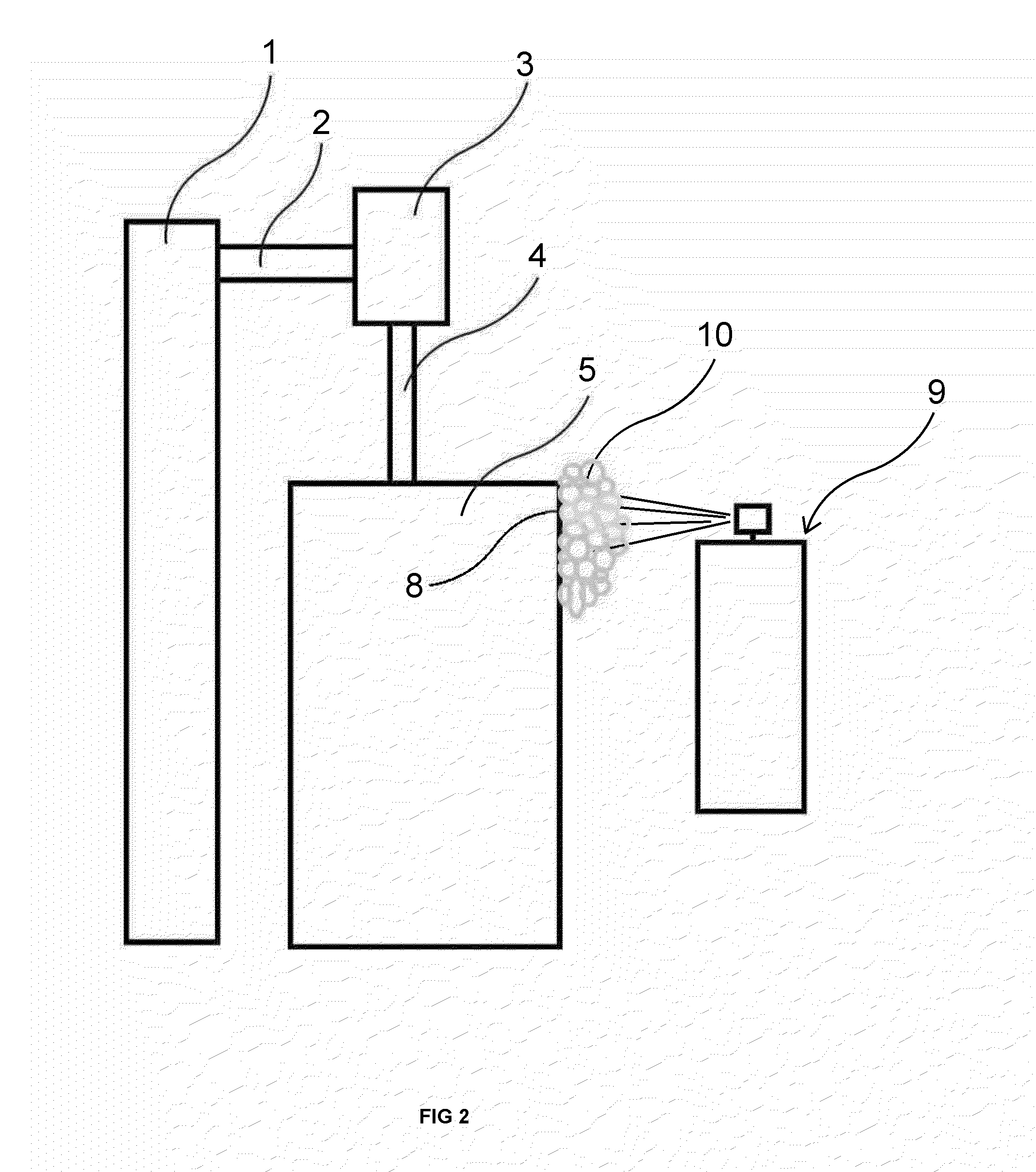
[0030]FIGS. 1-2 illustrate the leak detection system of the present invention, including the application of the foam. In FIG. 1 the CO2 pressurized bottle 1 is connected to a conventional pressure regulator 3 through hose 2. In operation, the service person will adjust pressure regulator 3 to the correct pressure for the system being tested. Hose 4 connects to sealed system 5. Thus, the pressure regulator 3 feeds CO2 from bottle 1 into sealed system 5 through hose 4. If one or more leaks are present in sealed system 5 then CO2 will escape out of the leak site(s) into the surrounding area. As illustrated, sealed system 5 has a leak at leak site 8 which leaks CO2 into the surrounding area.

[0031]After pressurizing system 5, a service person looking for leakage then moves CO2 detector 7 with sensor 6 round the sealed system 5. Where CO2 is leaking out of sealed system 5, sensor 6 detects the presence of this gas in the surrounding area. Detector 7 reads the sensor's voltage change that ...


PUM


Abstract

Detecting a leak from a site in a sealed system with a source of pressurized gas which is capable of passing through the site, a composition of matter which adheres to the surfaces of the system and which is capable of showing the presence of the gas escaping from the site. The method includes: injecting gas into the system to a pressure in excess of the surrounding pressure, and covering the external surface with the composition to identify the location of the site by the interaction of the escaping gas with the composition. The composition is foam that includes a surfactant which forms a least one bubble in the presence of escaping gas and an indicator which changes color in the presence of the escaping gas. The leak is an opening down to at least the size of a hole 0.001″ in diameter. A gas detector may also be used.

Description

CROSS-REFERENCE TO RELATED APPLICATIONS[0001]This application is a continuation of provisional application Ser. No. 61 / 759,782, entitled “Leak Detection Analyzer,” filed Feb. 1, 2013. This application is also a continuation-in-part of application Ser. No. 13 / 789,179 entitled “Leak Verification and Detection for Vehicle Fuel Containment Systems”, filed Mar. 7, 2013, which is a continuation-in-part of application Ser. No. 13 / 115,516, entitled “Leak Verification and Detection for Vehicle Fuel Containment Systems”, filed Mar. 25, 2011 which, in turn, is a continuation of provisional application Ser. No. 61 / 348,078, entitled “Leak Verification and Detection for Vehicle Fuel Containment Systems”, filed May 25, 2010. This application claims the priority to and the benefit of all four applications.FIELD OF INVENTION[0002]This invention relates to the field of leak detection, more particularly to finding small size leaks in sealed systems, quickly and accurately. This method uses pressurized...

Claims


Application Information

Patent Timeline
IPC IPC(8): G01N27/26
CPCG01N27/26G01M3/226G01M3/042
Inventor LEY, KENNETH D.PEDERSON, NEAL R.THOMA, STEVEN G.THOMPSON, BERNIE C.
Owner AUTOMOTIVE TEST SOLUTIONS
Why Eureka
Try Eureka