Eureka AIR delivers breakthrough ideas for toughest innovation challenges, trusted by R&D personnel around the world.

Optical connector and method for assembling same

Inactive Publication Date: 2014-09-11
HON HAI PRECISION IND CO LTD
View PDF67 Cites 5 Cited by
  • Summary
  • Abstract
  • Description
  • Claims
  • Application Information

AI Technical Summary

Benefits of technology

The present disclosure relates to an optical connector and a method for assembling the optical connector. The technical effect of the patent is to address the limitations of current optical connectors and methods of assembly, such as the possibility of the optical emitter and optical receiver being contaminated during assembly. The present invention provides an optical connector and method for assembly that addresses these limitations.

Problems solved by technology

The lens member is usually fixed to the support member by an adhesive, which may overflow and contaminate optical portions of the lens member during an assembling process.

Method used


Image

  • Optical connector and method for assembling same
  • Optical connector and method for assembling same
  • Optical connector and method for assembling same

Examples


Embodiment Construction

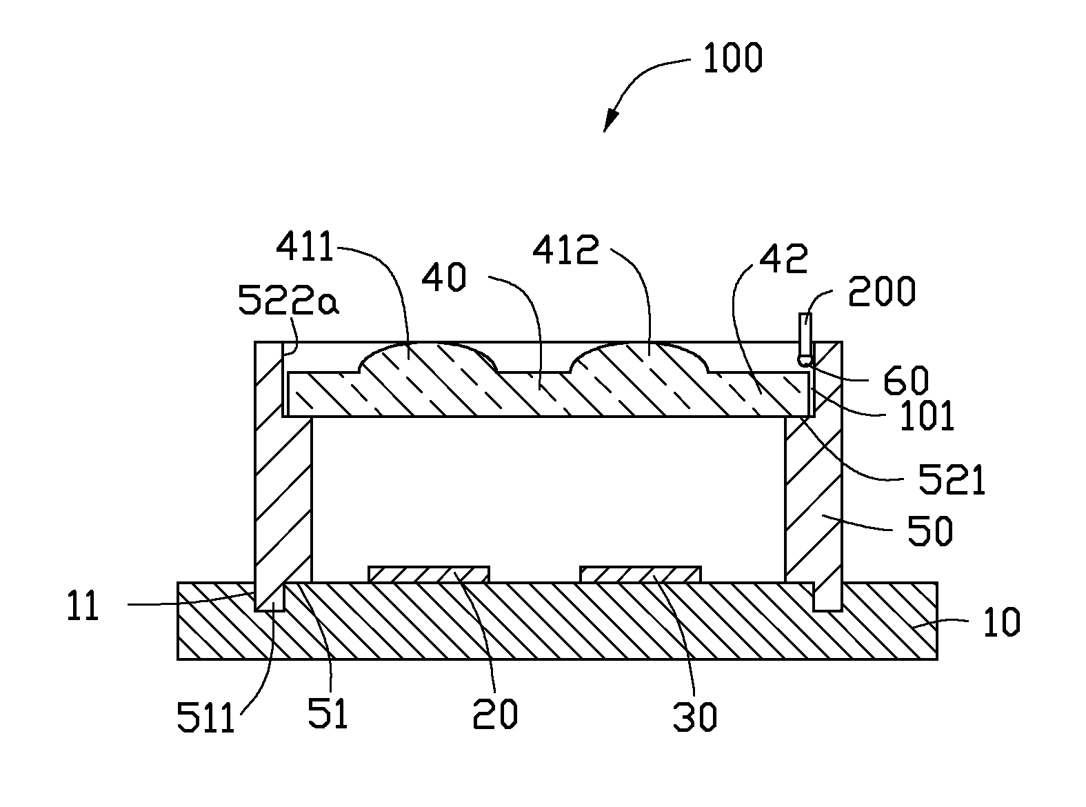
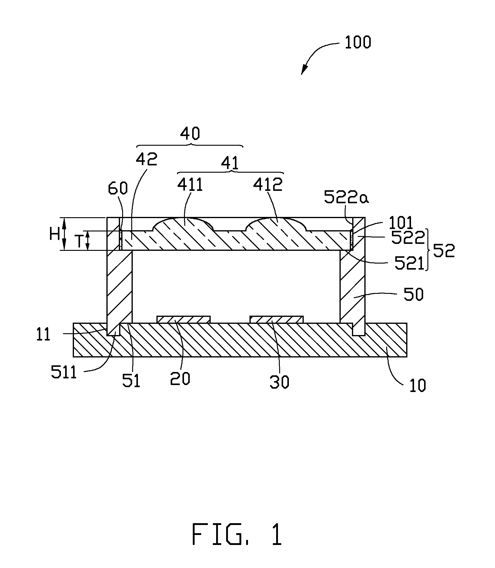
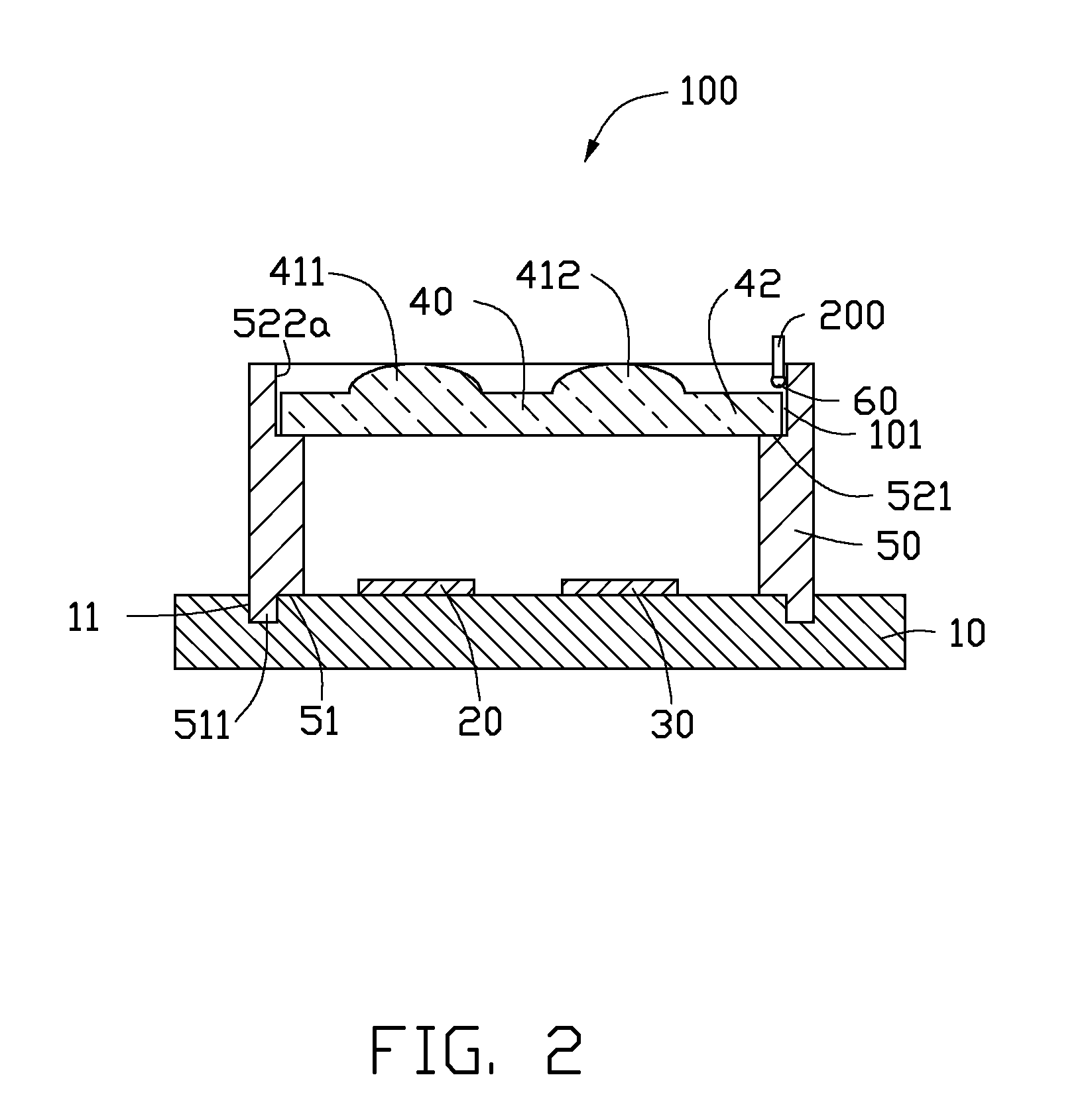
[0009]FIG. 1 shows one embodiment of an optical connector 10. The optical connector 10 includes substrate 10, an optical emitter 20, an optical receiver 30, a lens member 40, and a support member 50. The optical emitter 20 and the optical receiver 30 are positioned on and electrically connected to the substrate 10, the support member is positioned on the substrate 10, and the lens member 40 is supported above the optical emitter 10 and the optical receiver 20 by the support member 50.

[0010]The substrate 10 provides power and electrical signals to the optical emitter 20 and the optical receiver 30 and also receives electrical signals from the optical emitter 20 and the optical receivers 30.

[0011]The optical emitter 20 converts electrical signals (typically carrying information) into corresponding optical signals and emitting the optical signals. The optical receiver 30 is configured for receiving optical signals (typically modulated with information) and converting the optical signal...


PUM


Abstract

An optical connector includes a substrate, an optical emitter, an optical receiver, a support member, and a lens member. The optical emitter and the optical receiver are electrically connected to the substrate. The support member includes a lower end connected to the substrate and an upper end away from the substrate. The upper end includes a supporting end and a protrusion protruding from the supporting surface. The lens member includes a lens portion and an assembling portion surrounding the lens portion. A thickness of the assembling portion is less than a height of the protrusion relative to the supporting surface. The assembling portion abuts on the supporting surface and a slit is formed between a peripheral side surface of the assembling portion and an inner side surface of the protrusion. An adhesive is distributed in the slit to adhere the lens member to the support member.

Description

BACKGROUND[0001]1. Technical Field[0002]The present disclosure relates to communication apparatus and, particularly, to an optical connector and a method for assembling the optical connector.[0003]2. Description of Related Art[0004]Optical connectors include a substrate, an optical emitter, an optical receiver, a lens member, and a support member. The optical emitter and the optical receiver are positioned on the substrate, the support member is positioned on the substrate, and the lens member is supported on the support member and optically aligned with the optical emitter and the optical receiver. The lens member is usually fixed to the support member by an adhesive, which may overflow and contaminate optical portions of the lens member during an assembling process.[0005]Therefore, what is needed is an optical connector and a method for assembling the optical connector addressing the limitations described.BRIEF DESCRIPTION OF THE DRAWINGS[0006]The components of the drawings are no...

Claims


Application Information

Patent Timeline
IPC IPC(8): G02B6/42
CPCG02B6/4204G02B6/4246G02B6/4253
Inventor LAI, CHIH-CHEN
Owner HON HAI PRECISION IND CO LTD
Why Eureka
Eureka Blog
Learn More