Polarization-Multiplexed Optical Transmission System, Polarization-Multiplexed Optical Transmitter, and Polarization-Multiplexed Optical Receiver

a polarization-multiplexed optical and transmission system technology, applied in the direction of polarization multiplex systems, multi-channel communication, electromagnetic transmission, etc., can solve the problem of unable to determine which of the x-polarization component and the y-polarization component from the transmission side is extracted to the two ports, and unable to completely prevent the singularity problem. to achieve the effect of preventing signal quality degradation and high-reliability

Inactive Publication Date: 2012-05-31
HITACHI LTD
View PDF4 Cites 90 Cited by
  • Summary
  • Abstract
  • Description
  • Claims
  • Application Information

AI Technical Summary

Benefits of technology

[0056]The present invention can solve the singularity problem in optical polarization multiplexing and splitting transmission and to provide a high-speed and highly reliable polarization multiplexing and splitti

Problems solved by technology

It is difficult to completely prevent the singularity problem because the optical fiber transmission path causes a slight polarization-dependent loss and therefore the polarization orthogonality is slightly lost.
As another problem, it is unsure which of the X-polarization component and the

Method used


Image

  • Polarization-Multiplexed Optical Transmission System, Polarization-Multiplexed Optical Transmitter, and Polarization-Multiplexed Optical Receiver
  • Polarization-Multiplexed Optical Transmission System, Polarization-Multiplexed Optical Transmitter, and Polarization-Multiplexed Optical Receiver
  • Polarization-Multiplexed Optical Transmission System, Polarization-Multiplexed Optical Transmitter, and Polarization-Multiplexed Optical Receiver

Examples


first embodiment

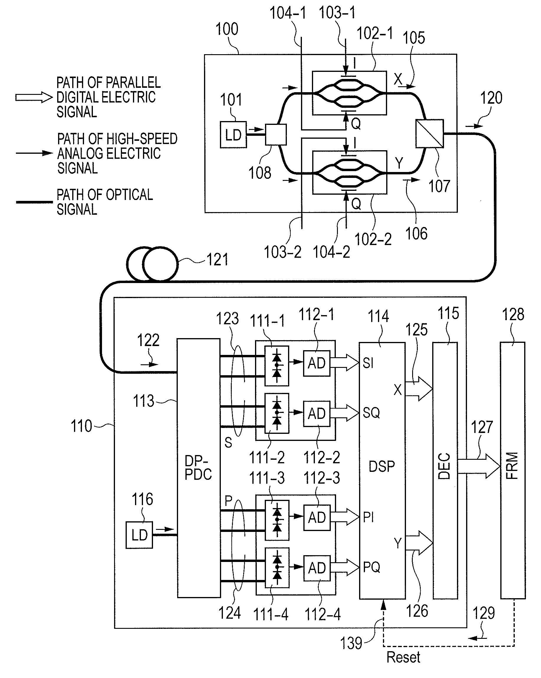
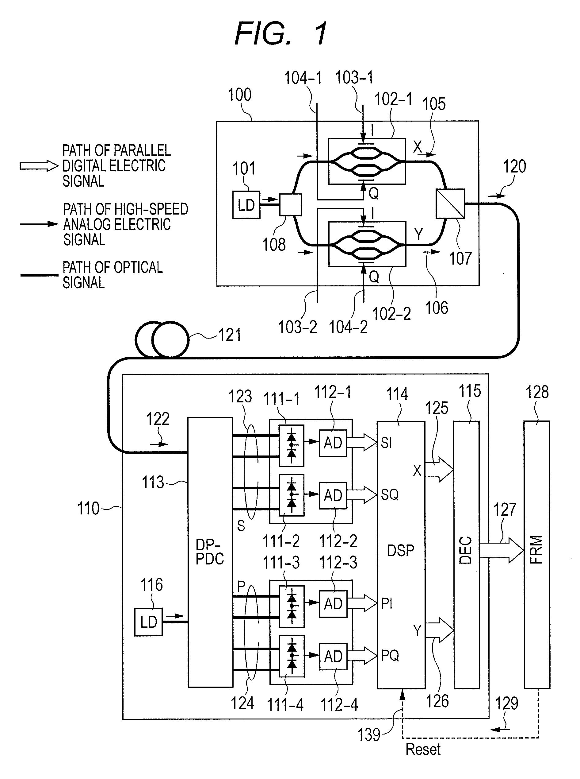
[0075]FIG. 5 is a configuration diagram showing a digital coherent polarization-multiplexed transmission system according to the invention. As shown in FIG. 5, a polarization-multiplexed optical transmitter 200 according to the embodiment outputs a polarization-multiplexed optical transmission signal 212 according to the embodiment. The optical transmission signal 212 is transmitted through an optical fiber transmission path 121. A polarization diversity coherent optical receiver 215 according to the embodiment receives the optical transmission signal 212 as a polarization-multiplexed received optical signal 213 according to the embodiment. In the following drawings, an outline arrow represents the path of a digital signal. A thin line represents the path of a high-speed analog electric signal. A thick line represents the path of an optical signal. A broken line represents the path of a low-speed control signal. Throughout the drawings, the same parts or components as those of the r...

second embodiment

[0097]FIG. 9 is a configuration diagram showing a polarization-multiplexed optical transmitter according to the invention. The example shows another method of generating a frequency shift signal. As described with reference to FIGS. 6C and 6D, the embodiment may modulate X-polarization and Y-polarization components using the signal points that slowly rotate at mutually different rates. The example in FIG. 9 directly generates an X-polarization modulation signal using a rotational multilevel encoding table 232 without using multiplication.

[0098]In a multilevel encoding circuit 230 according to the embodiment, an encoding logic circuit 231 outputs an intermediate sign 235-1 for the X-polarization component corresponding to an input information signal. The intermediate sign is used for the description and need not be used for the implementation. The following description assumes 4-value modulation using four values where d is set to 0 through 3. A clock circuit 233 outputs an index num...

fourth embodiment

[0103]FIG. 13 is an explanatory diagram showing a polarization-multiplexed optical transmitter 200 according to the invention. The example uses analog operations to generate the above-mentioned rotating multilevel signal points without using a digital operation or a high-speed DA converter. The configuration directly replaces the components in FIG. 5 with analog operations. A complex analog multiplier 252 complex-multiplies a complex analog multilevel signal 251 input to the transmitter by a sine wave for the frequency Δf supplied from a frequency-agile sine wave oscillator (low-frequency analog oscillator) 250. As a result, the frequency shift is generated. Specifically, the frequency-agile sine wave oscillator 250 outputs a signal that is used as a cosine wave cos (2πΔft). A 90-degree phase shifter 254 converts the output signal into a sine wave sin (2πΔft). The cosine wave and the sine wave respectively correspond to the real part and the imaginal part of a complex sine wave sign...


PUM


Abstract

There is a need to prevent two receivers from converging on a state of receiving the same polarization state, fast start receivers, and ensure highly reliable operations. A polarization-multiplexed transmitter previously applies frequency shifts of frequencies +Δf and −Δf to X-polarization and Y-polarization digital information signals to be transmitted. Optical field modulators modulate and polarization-multiplex the signals. As a result, a frequency difference of 2Δf is supplied to X-polarization and Y-polarization components. A polarization diversity coherent optical receiver 215 receives the signal. A frequency estimation portion in a digital signal processing circuit detects a frequency difference signal in both polarization components. This signal is used to a polarization splitting circuit in the digital signal processing circuit.

Description

CLAIM OF PRIORITY[0001]The present application claims priority from Japanese patent application JP 2010-265203 filed on Nov. 29, 2010, the content of which is hereby incorporated by reference into this application.FIELD OF THE INVENTION[0002]The present invention relates to a polarization-multiplexed optical transmission system, a polarization-multiplexed optical transmitter, and a polarization-multiplexed optical receiver. More particularly, the invention relates to an optical transmitter to transmit optical information using optical fiber or, in more detail, to apply polarization multiplexing to an optical signal modulated by an information signal, an optical receiver having a function of receiving and separating the optical signal, and an optical transmission system combining both.BACKGROUND OF THE INVENTION[0003]Ultra high-speed optical fiber transmission generally uses a wavelength division multiplexing (WDM)transmission technique that transmits multiple optical signals with di...

Claims


Application Information

Patent Timeline
IPC IPC(8): H04J14/06H04B10/06H04B10/04H04B10/2507H04B10/516H04B10/61H04J3/00H04J14/00H04J14/04
CPCH04B10/532H04J14/06H04B10/614
Inventor KIKUCHI, NOBUHIKO
Owner HITACHI LTD
Why Eureka
Try Eureka