Expandable implant

a technology of expandable implants and implants, applied in the field of expandable implants, can solve the problems of patients' substantial pain and discomfort, and achieve the effect of preventing over-insertion of implants

Active Publication Date: 2014-09-11
STRYKER EURO OPERATIONS HLDG LLC
View PDF11 Cites 139 Cited by
  • Summary
  • Abstract
  • Description
  • Claims
  • Application Information

AI Technical Summary

Benefits of technology

[0009]A third aspect of the invention includes yet another expandable implant system comprising an implant with top and bottom plates each having a bone-contacting surface and an opposing inner surface, the inner surface of each of the top and bottom plates including a ramp surface. The system also comprises an actuator situated between the inner surfaces of the top and bottom plates, the actuator being removable from between the top and bottom plates after implantation of the implant, and an expansion member removably engageable with the actuator and located between the inner surfaces of the top and bottom plates, the expansion member having angled surfaces mating with the ramp surfaces of the top and bottom plates so that, upon actuation of the actuator, the expansion member moves along a longitudinal axis of the implant to expand the top and bottom plates from a first dimension to a second greater dimension, wherein the top and bottom plates are securable at varying angles to one another depending on the amount of movement of the expansion member along the ramp surfaces, the angle between the top and bottom plates accommodating the natural lordosis between adjacent vertebral bodies. In one embodiment of this third aspect, at least one of the top and bottom plates is also associated with a flange having an aperture adapted to receive a fixation member, the flange extending beyond the at least one of the top and bottom plates to prevent over insertion of the implant into an intervertebral disc space.

Problems solved by technology

Common spinal maladies, such as degeneration of an intervertebral disc of the spine (commonly referred to as Degenerative Disc Disease), spondylosis, spinal stenosis, disc herniation, retrolisthesis, discogenic back pain, or other like conditions may result in substantial pain and discomfort for a patient.

Method used


Image

  • Expandable implant
  • Expandable implant
  • Expandable implant

Examples


Embodiment Construction

[0014]In describing the preferred embodiments of the invention(s) illustrated and to be described with respect to the drawings, specific terminology will be used for the sake of clarity. However, the invention(s) is not intended to be limited to any specific terms used herein, and it is to be understood that each specific term includes all technical equivalents, which operate in a similar manner to accomplish a similar purpose.

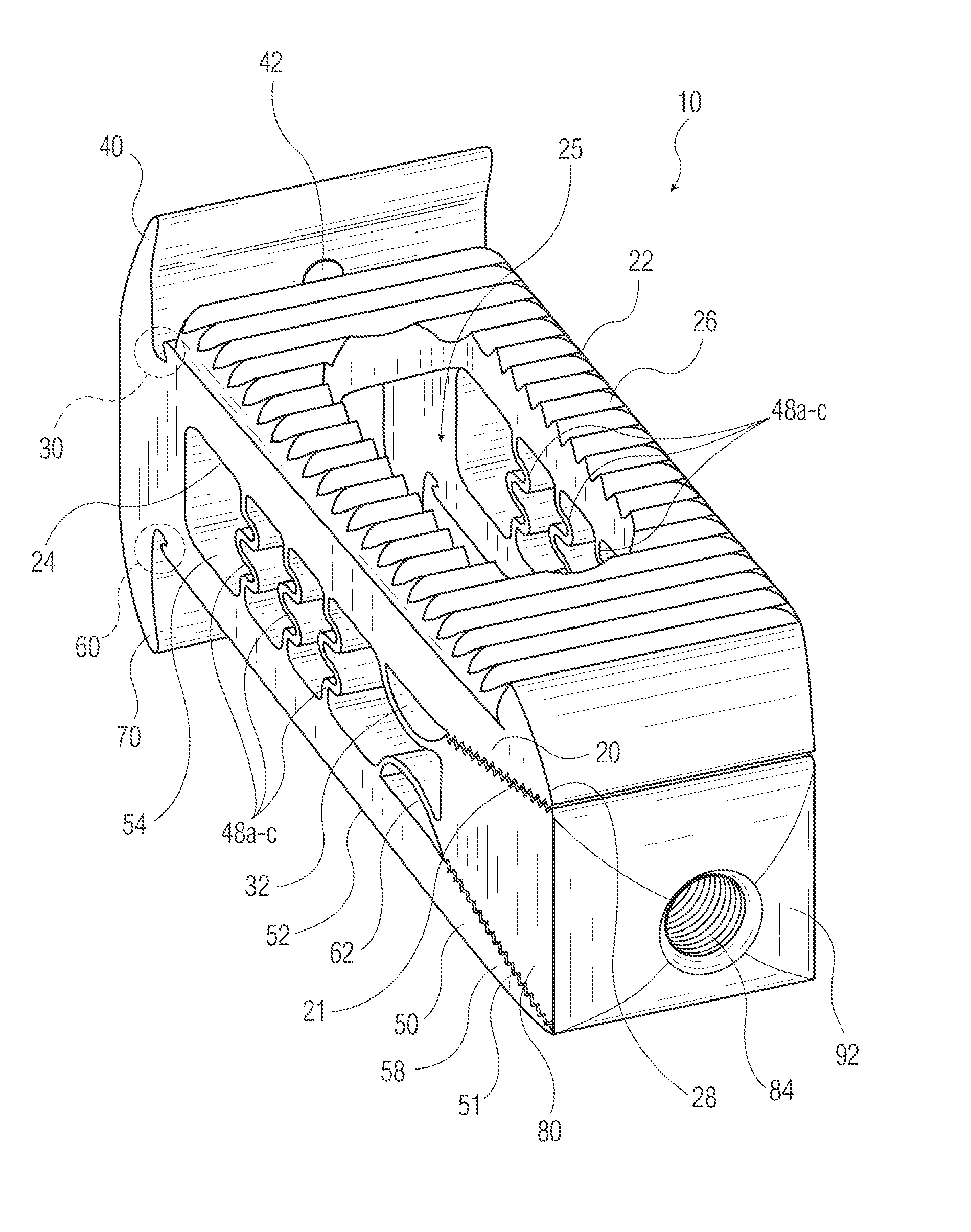
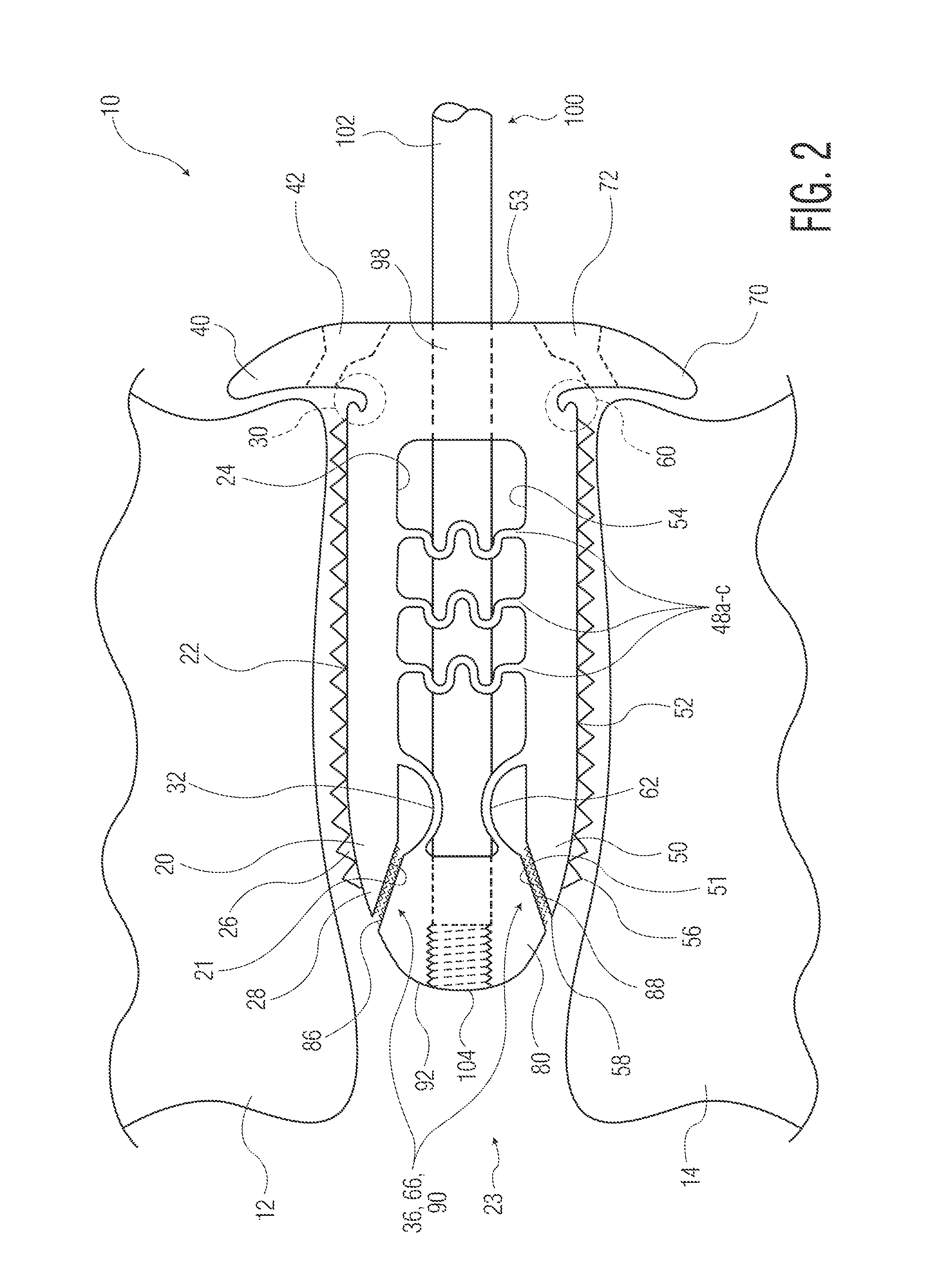
[0015]Referring to FIG. 1, an implant 10 is shown as generally having top and bottom plates 20, 50 with ramp surfaces 21, 51 thereon, and at least one expansion member 80 for engaging the ramp surfaces 21, 51 and expanding the implant 10 (e.g., to place the same in a lordotic state). The implant 10 may be implanted between adjacent vertebral bodies 12, 14, as shown in FIGS. 2-5, to aid in fusion of such bodies and immobilization of the spine at the implantation site. This may help to relieve pain associated with one of the chronic degenerative spinal condition...


PUM


Abstract

An expandable implant system is disclosed in which the system comprises an implant with: (1) top and bottom plates, (2) ramp surfaces formed on inner surfaces of the plates, and (3) an expansion member situated between the plates. An actuator also forms part of the system, the actuator being removable from between the top and bottom plates after implantation of the implant. The expansion member has a set of angled surfaces for mating with the ramp surfaces of the plates and, upon movement of the expansion member along a longitudinal axis of the implant, the top and bottom plates expand from a first dimension to a second greater dimension. The top and bottom plates are also securable at varying angles to one another depending on the amount of movement of the expansion member along the ramp surfaces.

Description

CROSS REFERENCE TO RELATED APPLICATIONS[0001]This application claims the benefit of the filing date of U.S. Provisional Patent Application No. 61 / 775,909, filed Mar. 11, 2013, the disclosure of which is hereby incorporated herein by reference.BACKGROUND OF THE INVENTION[0002]The present invention(s) relates to expandable implants and tools for the insertion of such implants. More particularly, the invention(s) pertains to an expandable spinal implant having opposed plates, which are expandable via the interaction between a wedge member and ramped surfaces included on the plates. An insertion instrument used for implantation of the implant, and methods of utilizing the same, are also disclosed.[0003]Common spinal maladies, such as degeneration of an intervertebral disc of the spine (commonly referred to as Degenerative Disc Disease), spondylosis, spinal stenosis, disc herniation, retrolisthesis, discogenic back pain, or other like conditions may result in substantial pain and discomf...

Claims


Application Information

Patent Timeline
Patent Type & Authority Applications(United States)
IPC IPC(8): A61F2/44
CPCA61F2/447A61F2/4455A61F2/4611A61F2002/2835A61F2002/30136A61F2002/30281A61F2002/30462A61F2002/30494A61F2002/30556A61F2002/30578A61F2002/30579A61F2002/30593A61F2002/30772A61F2002/30774A61F2002/30904
Inventor ALHEIDT, THOMAS A.
Owner STRYKER EURO OPERATIONS HLDG LLC
Why Eureka
Try Eureka