Method of reducing rotation noise in a magnetoelastic torque sensing device

a technology of magnetoelastic torque and sensing device, which is applied in the direction of magnetoelectronic devices, instruments, manufacturing tools, etc., can solve the problems that negatively affect the accuracy of prior art torque sensing devices, and achieve the effect of eliminating rotation noise, no rotation noise, and eliminating rotation noise in the transducer

Active Publication Date: 2014-09-18
METHODE ELETRONICS INC
View PDF6 Cites 8 Cited by
  • Summary
  • Abstract
  • Description
  • Claims
  • Application Information

AI Technical Summary

Benefits of technology

[0016]It is a principal object of the present invention to provide a method for magnetizing a torque transducer wherein the magnetization field direction is adjusted during the magnetization process to eliminate rotation noise in the transducer.
[0017]It is another object of the present invention to provide a magnetoelastic torque transducer that produces essentially no rotation noise.
[0018]It is yet another object of the present invention to provide a system for magnetizing a torque transducer wherein the magnetization field direction is adjusted during the magnetization process to eliminate rotation noise in the transducer.

Problems solved by technology

The torque sensing devices rely on the principle that, because the magnetic field sensors are not capable of sensing magnetic field components that are perpendicular to their sensitive directions, each magnetic field sensor produces no output when the transducer is in the quiescent state.
However, those prior art transducers often have physical irregularities that may result from inconsistent alloy composition or crystal displacements, or may be otherwise unintentionally introduced during the fabrication process.
Such irregularities can result in localized areas within the magnetoelastically active region in which the direction and / or strength of the magnetic field varies from its theoretical value.
Such magnetic field variations are referred to as rotation noise, and can negatively affect the accuracy of prior art torque sensing devices.

Method used


Image

  • Method of reducing rotation noise in a magnetoelastic torque sensing device
  • Method of reducing rotation noise in a magnetoelastic torque sensing device
  • Method of reducing rotation noise in a magnetoelastic torque sensing device

Examples


Embodiment Construction

[0032]Several preferred embodiments of the invention are described for illustrative purposes, it being understood that the invention may be embodied in other forms not specifically shown in the drawings. The figures herein are provided for exemplary purposes and are not drawn to scale.

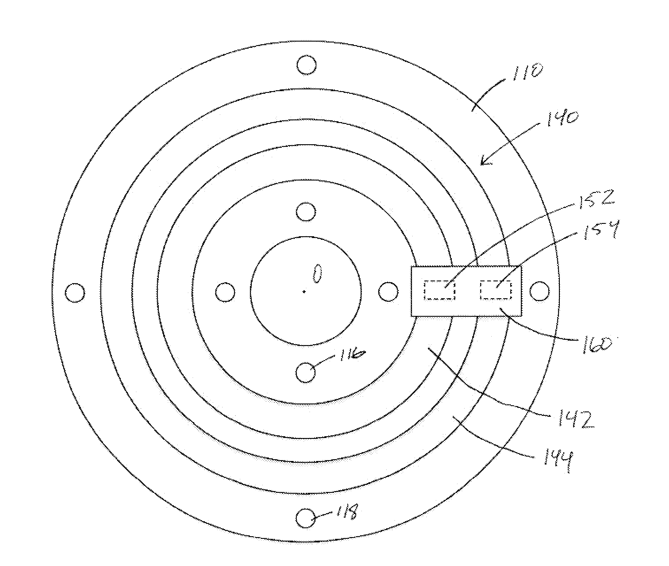
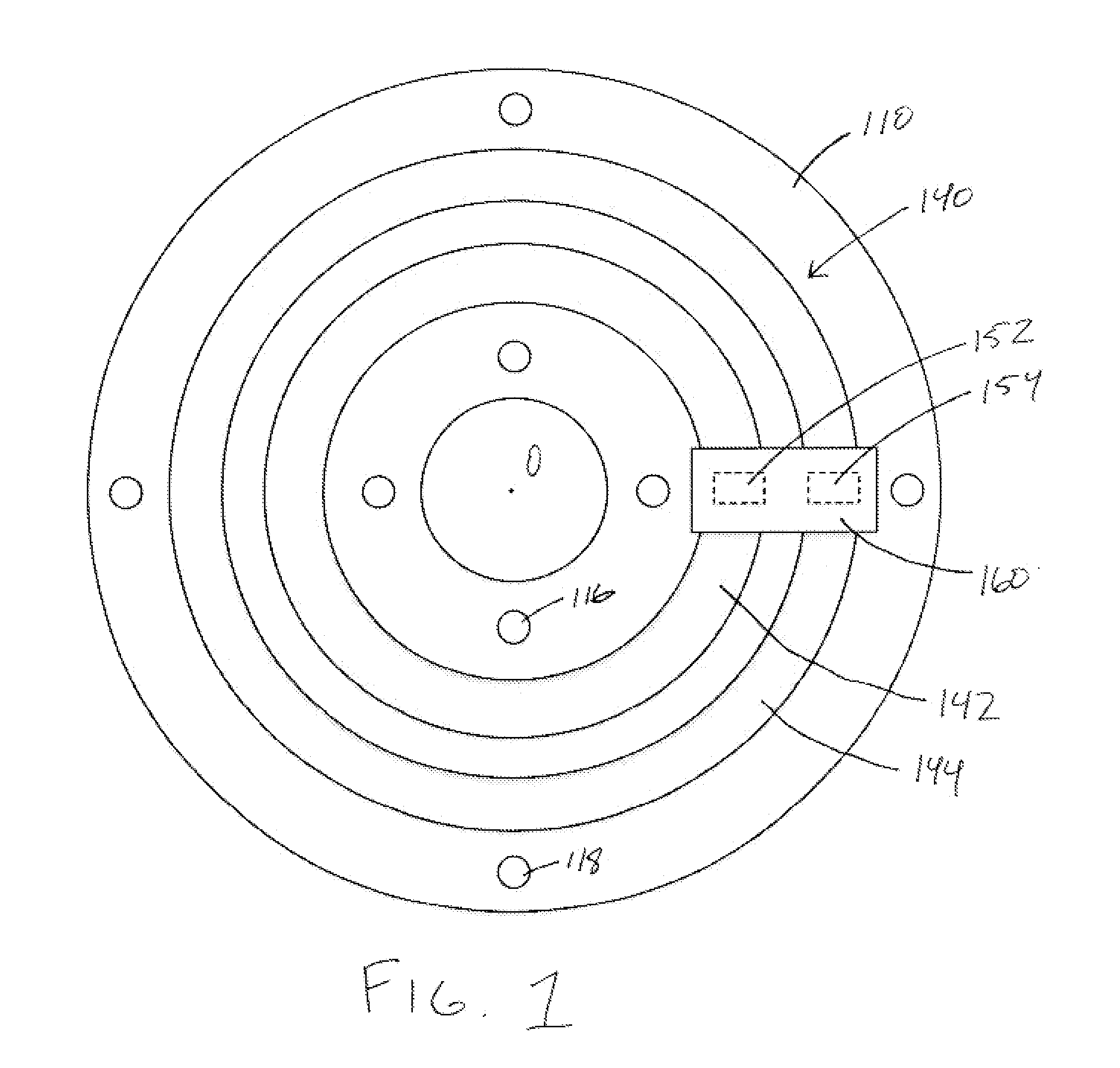
[0033]Turning first to FIG. 1, shown therein is a top view of an exemplary disk-shaped member (i.e., disk) 110, which may be magnetized in accordance with the present invention. It should be noted that the invention can also be used with a shaft as the torque transducing element. The disk 110 is formed of ferromagnetic material and is, or at least includes, a magnetoelastically active region 140. The material selected for forming the disk 110 must be at least ferromagnetic to ensure the existence of magnetic domains for at least forming a remanent magnetization in the magnetoelastically active region 140, and must be magnetostrictive such that the orientation of magnetic field lines in the magnetoelast...


PUM

PropertyMeasurementUnit
thicknessaaaaaaaaaa
magnetoelasticaaaaaaaaaa
magnetic fieldsaaaaaaaaaa

Abstract

A system and method for creating one or more magnetically conditioned regions on a rotatable shaft or disk-shaped torque sensing element, wherein rotation noise produced by the element due to magnetic field variations is substantially negated. Upon magnetization of the torque sensing element, rotation noise produced by the magnetically conditioned region is measured. Adjustment factors are calculated based on the measured rotation noise, and the adjustment factors are used to adjust a magnetic field source during subsequent magnetization of the torque sensing element.

Description

BACKGROUND OF THE INVENTION[0001]1. Field of Invention[0002]The present invention relates to a system and method for reducing rotation noise in a magnetoelastic torque sensing device. More specifically, the present invention relates to a system and method for creating one or more magnetically conditioned regions on a rotatable shaft or disk-shaped torque sensing element, wherein rotation noise produced by the element due to magnetic field variations is substantially negated.[0003]2. Description of the Related Art[0004]In the control of systems having rotating drive shafts, torque and speed are fundamental parameters of interest. Therefore, the sensing and measurement of torque in an accurate, reliable, and inexpensive manner has long been a primary objective of such control system designs.[0005]U.S. Pat. Nos. 5,351,555 and 5,520,059 to Garshelis, the entireties of which are incorporated by reference herein, describe torque sensing devices that include a shaft, and a ring of magnetoe...

Claims


Application Information

Patent Timeline
Patent Type & Authority Applications(United States)
IPC IPC(8): G01L3/10
CPCG01L3/102G01D5/145G01D5/2448G01L3/103Y10T29/4902Y10T29/53196
Inventor MORAN, TIMOTHY J.URSETTA, FRANK
Owner METHODE ELETRONICS INC
Why Eureka
Try Eureka