
Apparatus and non-transitory computer-readable medium

a computer-readable medium and apparatus technology, applied in the direction of metal working apparatuses, etc., can solve the problems of wasting a whole sheet, difficult to automatically determine whether or not the pattern is a black dot, and noise on the data

Active Publication Date: 2014-09-18
BROTHER KOGYO KK
View PDF1 Cites 20 Cited by
  • Summary
  • Abstract
  • Description
  • Claims
  • Application Information

AI Technical Summary

Benefits of technology

The disclosure is about a cutting plotter that can print patterns on sheets of material. It can automatically determine if the pattern is a black dot or a larger mark on the sheet. The mark on the sheet is also read by the scanner, which may affect the cutting data. The patent is about a device and computer software that can process image data and set a specific size for a pattern. It can also eliminate patterns that are not relevant and move the cutting device close to the sheet to cut the pattern. The technical effect of this invention is to improve the accuracy and efficiency of cutting patterns on sheets.

Problems solved by technology

There is sometimes a case where noise is on the data of image read by the scanner.
In this case, it is difficult to automatically determine whether or not the pattern is a black dot.
In this case, there is a possibility that processing may be applied to a part which normally requires no processing and that a whole sheet may be wasted.

Method used


Image

  • Apparatus and non-transitory computer-readable medium
  • Apparatus and non-transitory computer-readable medium
  • Apparatus and non-transitory computer-readable medium

Examples


Embodiment Construction

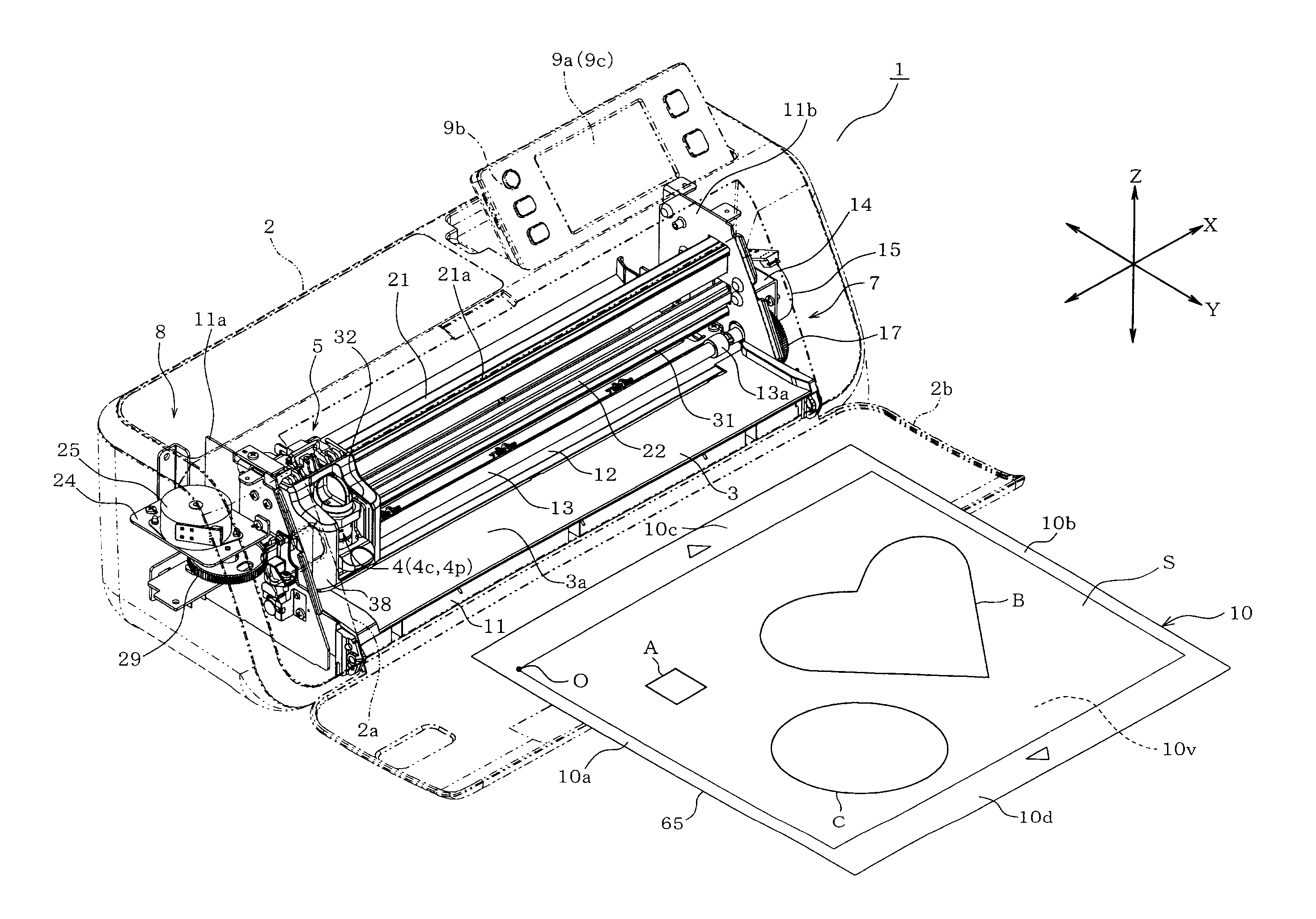
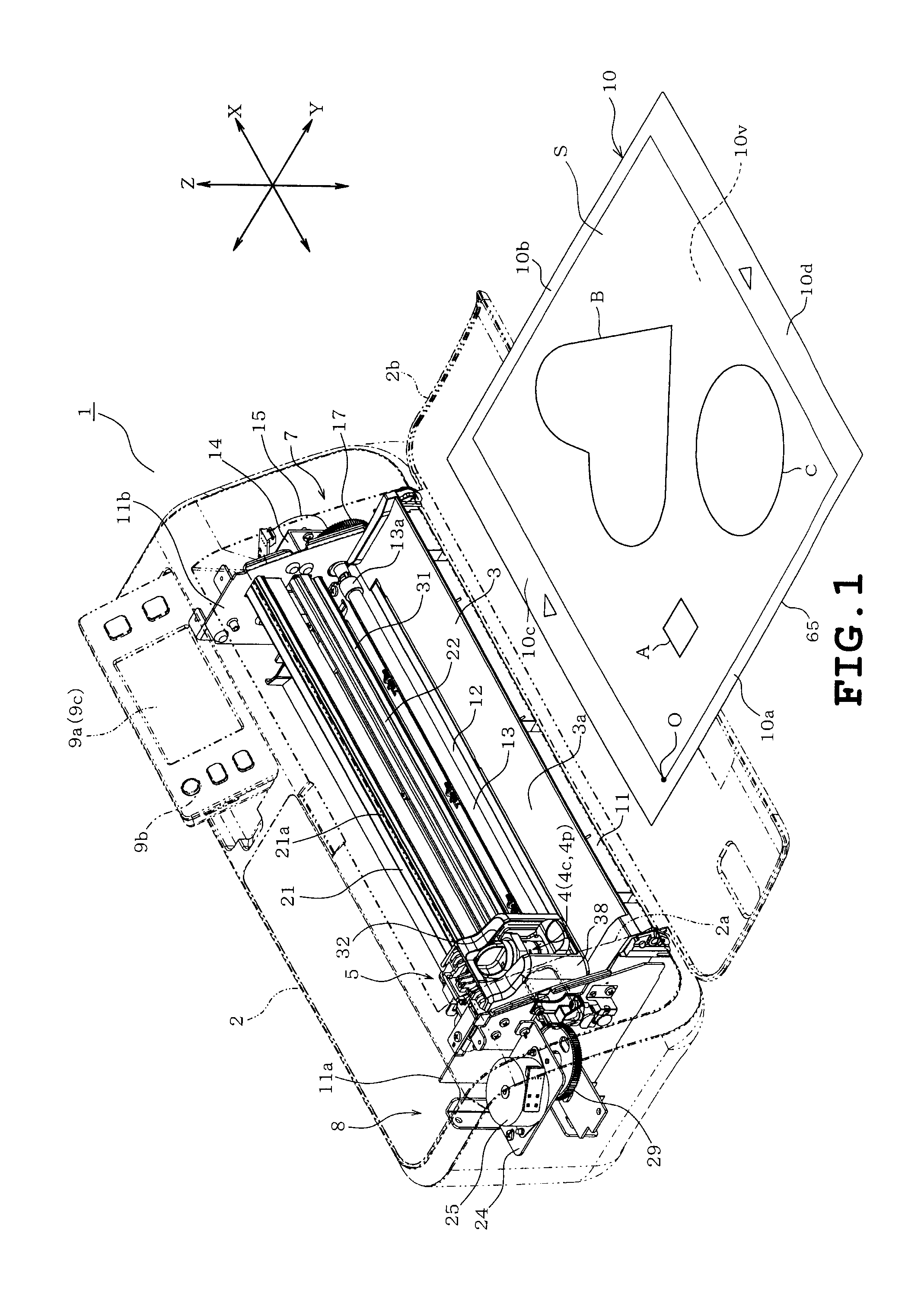
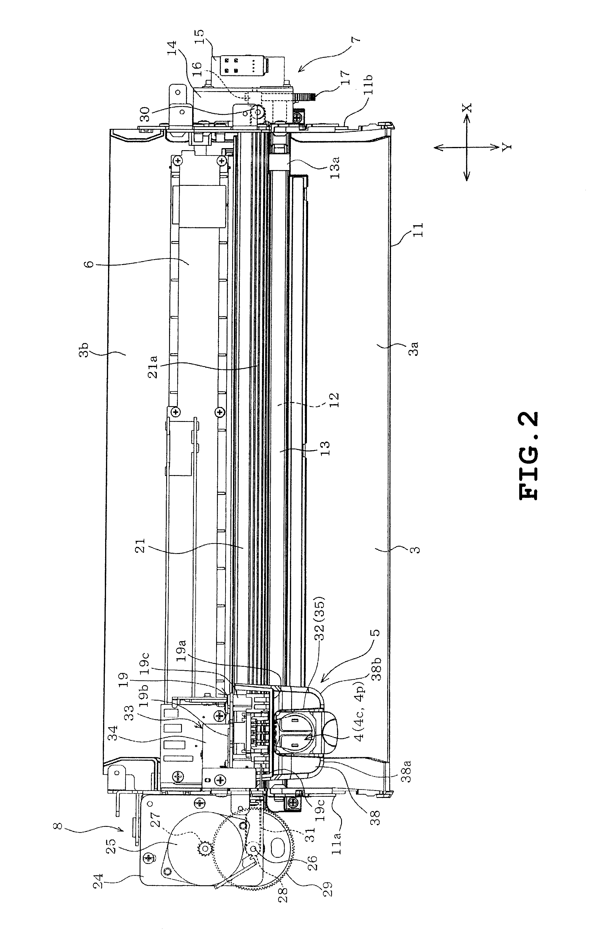
[0031]One example of an apparatus will be described with reference to the accompanying drawings. Referring to FIG. 1, a processing apparatus 1 is shown and includes a body cover 2 serving as a housing, a platen 3 provided in the body cover 2 and a processing head 5 on which a cartridge 4 is to be mounted. The processing apparatus 1 further includes a scanner 6 (see FIGS. 2 and 6) serving as an image obtaining unit.

[0032]In the processing apparatus 1, a plurality of cutter cartridges 4c and a plurality of pen cartridges 4p are prepared as the cartridge 4. One of the cartridges 4c and 4p is selectively attached to a cartridge holder 32 of a processing head 5 as will be described later. All the cartridges 4c and 4p include respective cases having substantially the same shape (see cases 50 in FIGS. 4A and 4B). All the cartridges 4c and 4p will be hereinafter referred to as “cartridge 4” for the sake of simplicity.

[0033]The processing apparatus 1 also includes a holding Member to hold an...


PUM

PropertyMeasurementUnit
Sizeaaaaaaaaaa
Transparencyaaaaaaaaaa

Abstract

An apparatus includes a cartridge holder configured to receive a pen or a cutter, a platen configured to receive an object, a moving mechanism configured to move the cartridge holder in a direction that the cartridge holder comes close to the platen, a read unit configured to read image data from the object, and a processor configured to instruct the apparatus to set a specific size of a pattern in the image data, eliminate, from the image data, one or more of specific patterns whose size is less or equal to the specific size, and instruct the moving mechanism to move the cartridge holder close to the platen, based on the image data after eliminating one or more of specific patterns from the read image data.

Description

CROSS-REFERENCE TO BELATED APPLICATIONS[0001]This application is based upon and claims the benefit or priority from the prior Japanese Patent Application No. 2013-051698 filed on Mar. 14, 2013, the entire contents of which are incorporated herein by reference.BACKGROUND[0002]1. Technical Field[0003]The present disclosure relates to an apparatus provided with a cartridge holder receiving a pen or a cutter and a non-transitory computer-readable medium storing data of instructions for the apparatus.[0004]2. Related Art[0005]Cutting plotters have been conventionally known as an apparatus automatically executing a cutting process. An object to be cut is a sheet-shaped object (paper sheet, for example). The sheet is held on a base material. More specifically, the base material is a holding member having an adhesive layer on a surface thereof. The sheet is applied to the adhesive layer. The cutting plotter moves the base material holding the sheet, in a first direction while holding both e...

Claims


Application Information

Patent Timeline
IPC IPC(8): B26F1/38B26D5/00
CPCB26D5/007B26F1/3813B26D5/02B26D7/015B26D2007/2678Y10T83/162Y10T83/849
Inventor TOKURA, MASASHI
Owner BROTHER KOGYO KK
Learn More