Soc system

a technology of system and chip, applied in the field of system on chip (soc) system, can solve the problems of complex architecture, high design cost, and inadequacies, and achieve the effect of high speed and short tim

Inactive Publication Date: 2009-05-28
ELECTRONICS & TELECOMM RES INST
View PDF9 Cites 13 Cited by
  • Summary
  • Abstract
  • Description
  • Claims
  • Application Information

AI Technical Summary

Benefits of technology

[0011]The present invention is directed to providing a System on Chip (SoC) system that efficiently combines a bus architecture capable of processing requests of processors to transfer a large amount of data in a short time with a network architecture capable of simultaneously processing data transfer requests of various devices, and thus is appropriate for processing a large amount of data at high speed.
[0012]The present invention is also directed to providing a SoC system that has a control path of peripheral devices and a data transfer path separated from each other, uses a memory structure physically divided according to data characteristics and data communication bandwidth requirement, allowing for a large amount of data transferred at high speed.

Problems solved by technology

However, the conventional SoC communication architecture can transfer data only through a single bus shared by several devices and thus can transfer only one piece of data at a time.
Such a reduction in the occupation ratio limits the transfer quantity of a master and thus is not appropriate for a multiprocessor-based system that must transfer a large amount of data between masters in a short time.
Therefore, such architecture does not solve a problem of a bandwidth constraint caused by sharing a physical wire when data is transferred between a master IP module and a slave IP module.
However, the architecture is complex, requires a high design cost, and is not appropriate for controlling a device requiring a short delay because of data transfer delay between a switch and a network interface.

Method used


Image

  • Soc system
  • Soc system
  • Soc system

Examples


Embodiment Construction

[0020]Hereinafter, exemplary embodiments of the present invention will be described in detail. However, the present invention is not limited to the embodiments disclosed below, but can be implemented in various forms. The following embodiments are described in order to enable those of ordinary skill in the art to embody and practice the present invention.

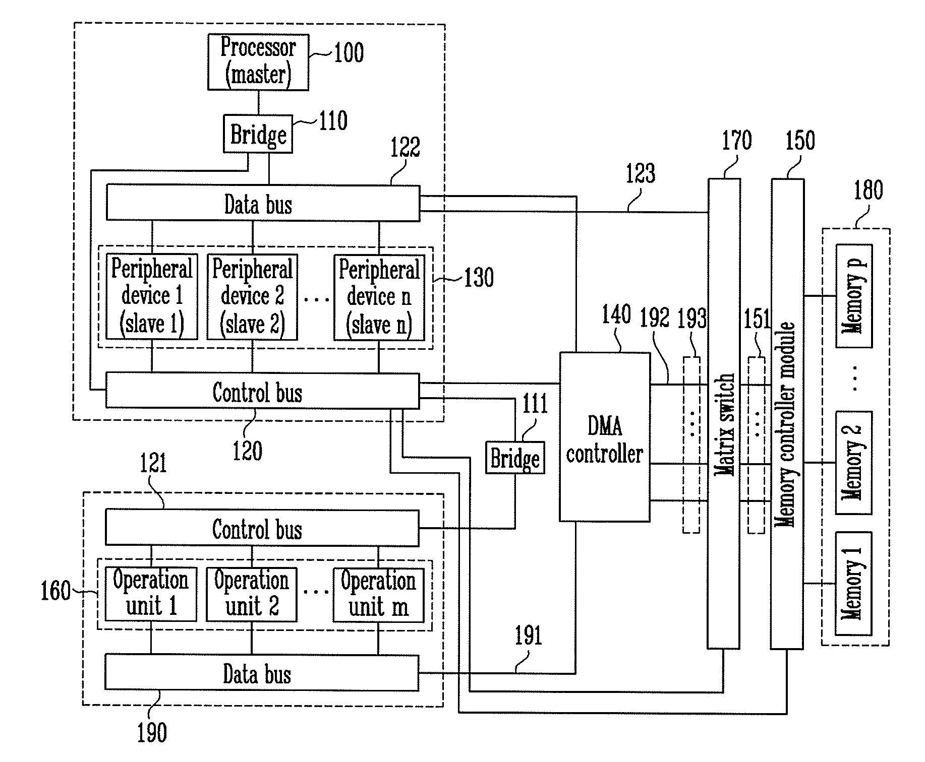
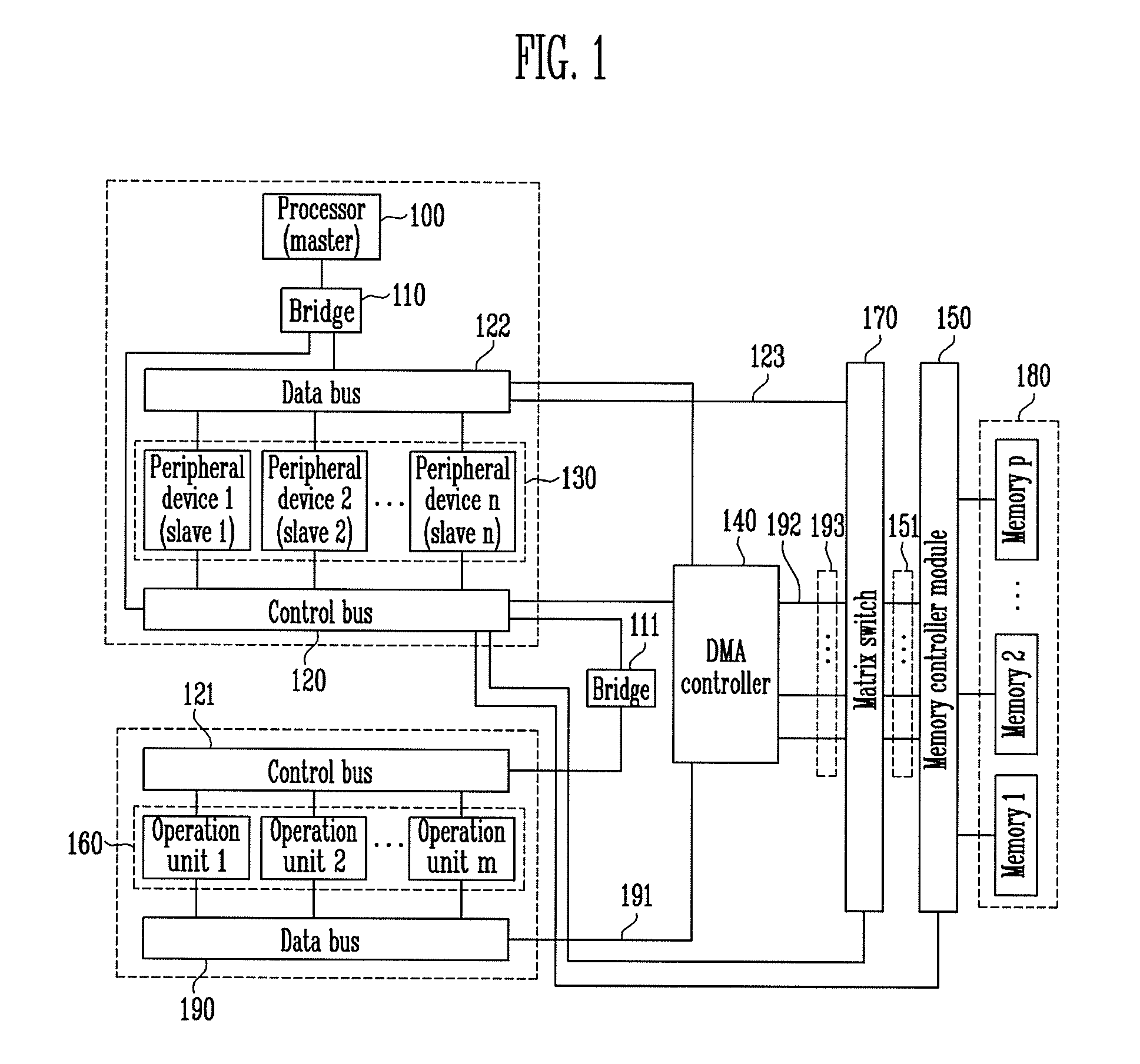
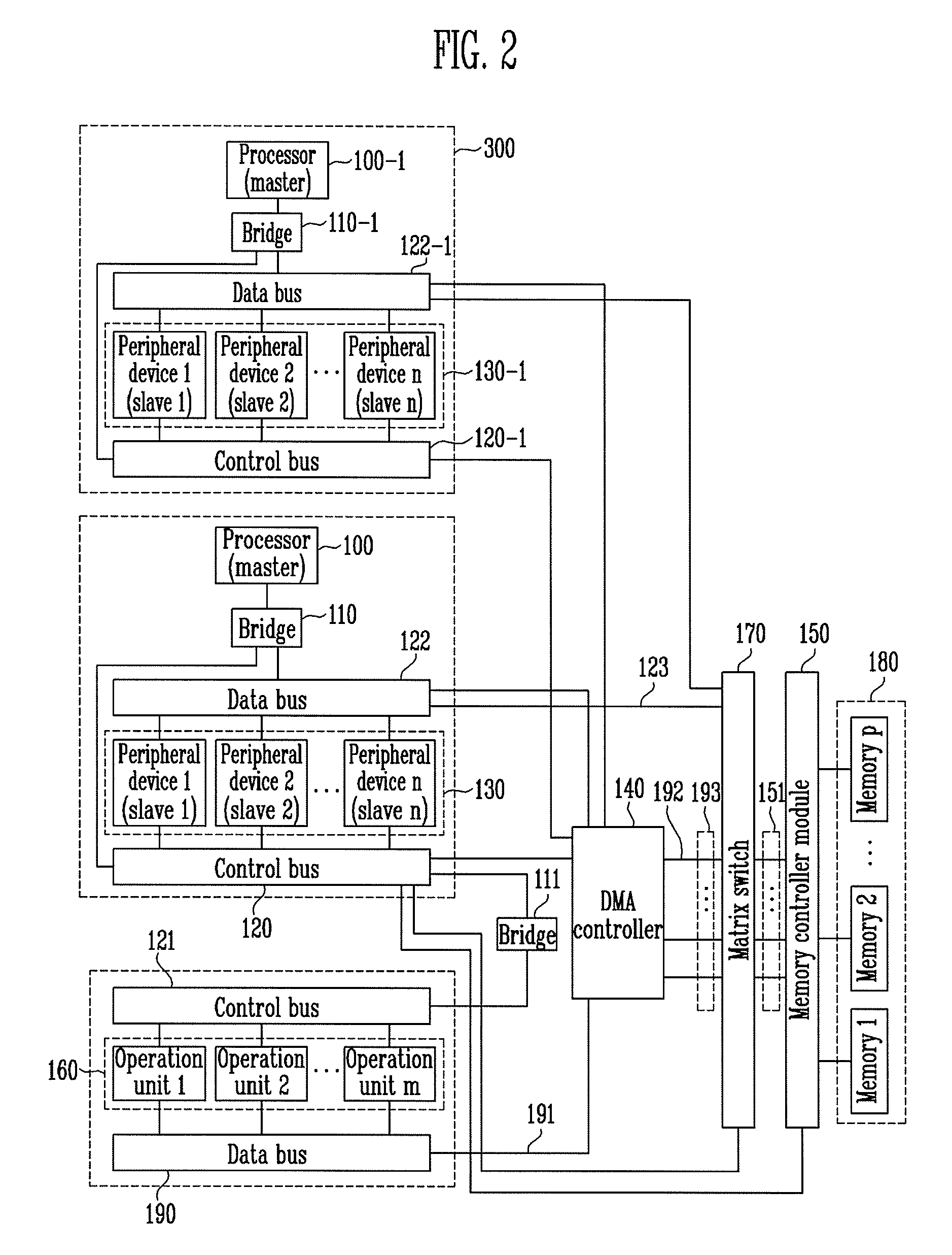
[0021]FIG. 1 is a block diagram of a System on Chip (SoC) architecture according to a first exemplary embodiment of the present invention, and FIG. 2 is a block diagram of a SoC architecture according to a second exemplary embodiment of the present invention. The SoC architecture shown in FIG. 2 is different from the SoC architecture shown in FIG. 1 in that it further includes a subsystem 300 connected through a bridge 111 and having an additional processor for system expansion. Other components are the same as those of the SoC architecture of FIG. 1 and thus denoted by the same reference numerals throughout the drawings.

[0022]Refer...


PUM


Abstract

Provided is a System on Chip (SoC) system for a multimedia system enabling high-speed transfer of a large amount of multimedia data and a processor to rapidly control a peripheral device. The SoC system includes a processor; a plurality of peripheral devices; a plurality of physically divided memories; a control bus for transferring a control signal from the processor to the peripheral devices and the memories; a data bus for transferring data between the processor, the peripheral devices and the memories; a bridge for coupling the control bus and the data bus to the processor; a plurality of memory controllers coupled to the control bus and controlling each of the memories; a Direct Memory Access (DMA) controller coupled to the data bus and the control bus and controlling data transfer between the peripheral devices and the memories; and a matrix switch coupled between the DMA controller and the memory controllers and enabling simultaneous multiple memory access.

Description

CROSS-REFERENCE TO RELATED APPLICATION[0001]This application claims priority to and the benefit of Korean Patent Application No. 2007-121656, filed Nov. 27, 2007, the disclosure of which is incorporated herein by reference in its entirety.BACKGROUND[0002]1. Field of the Invention[0003]The present invention relates to a System on Chip (SoC) system, and more particularly, to an SoC system for a multimedia system enabling high-speed transfer of a large amount of multimedia data and fast control of peripheral devices by a processor.[0004]The present invention is derived from the research supported by the IT R&D program of the Ministry of Information and Communication (Republic of Korea) and the Institute for Information Technology Advancement (Republic of Korea) [Project Management Number: 2006-S006-02, Project Title: Component / Module technology for Ubiquitous Terminals].[0005]2. Discussion of Related Art[0006]A conventional bus-based SoC communication architecture is simple and require...

Claims


Application Information

Patent Timeline
Patent Type & Authority Applications(United States)
IPC IPC(8): G06F13/28
CPCG06F13/28G06F13/1657G06F13/00G06F15/78
Inventor CHUN, IK JAEROH, TAE MOONKIM, JONG DAE
Owner ELECTRONICS & TELECOMM RES INST
Why Eureka
Try Eureka