Discharge container

a discharge container and discharge port technology, applied in the field of discharge containers, can solve the problems of difficult to completely empty viscous contents, and achieve the effects of preventing leakage from the discharge port, reducing material costs, and reducing the degree of freedom of setting

Active Publication Date: 2014-09-18
YOSHINO KOGYOSHO CO LTD
View PDF3 Cites 31 Cited by
  • Summary
  • Abstract
  • Description
  • Claims
  • Application Information

AI Technical Summary

Benefits of technology

[0033]According to the discharge container, quality of the contents can be secured, and leakage from the discharge port can be prevented without increasing the number of parts.
[0034]In addition, the discharge container can obtain a secure check valve function by a flow suppressing action of a suppressing section with respect to the contents disposed inside the discharge film. For this reason, the discharge film can form a conventional thin slit valve structure. In addition, a shape of the discharge film can also be freely set to a desired shape. As a result, as a use amount of the expensive soft elastic material that forms the discharge film is reduced, the material cost can be reduced, and the degree of freedom in setting the structure of the discharge film can be increased.
[0035]In addition, the suppressing section can be stably and securely disposed at a position near the inside of the discharge film. For this reason, the suppressing action with respect to the suppressing section can be effectively and efficiently applied to the check valve function of the discharge film.
[0036]Further, the baffle plate piece can be securely disposed at a position near the slit, which is the opening / closing hole section of the discharge film. For this reason, the suppressing action of the suppressing section with respect to the contents can be extremely effectively exhibited. Accordingly, the discharge film can exhibit a stable and secure check valve function.

Problems solved by technology

In general, it is not easy to completely empty viscous contents.

Method used


Image

  • Discharge container
  • Discharge container
  • Discharge container

Examples


first embodiment

[0046]Hereinafter, a discharge container according to a first embodiment of the present invention will be described with reference to the accompanying drawings.

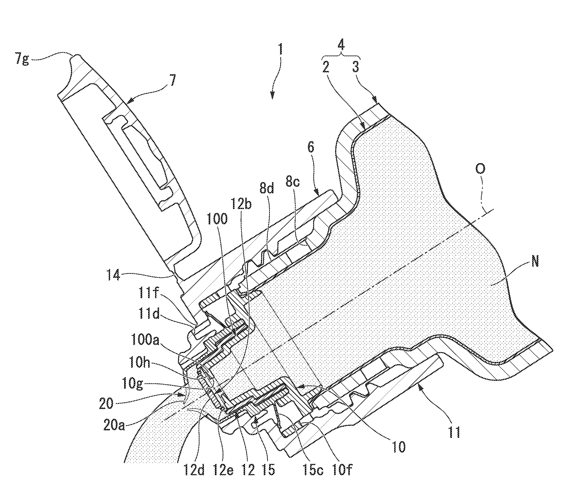
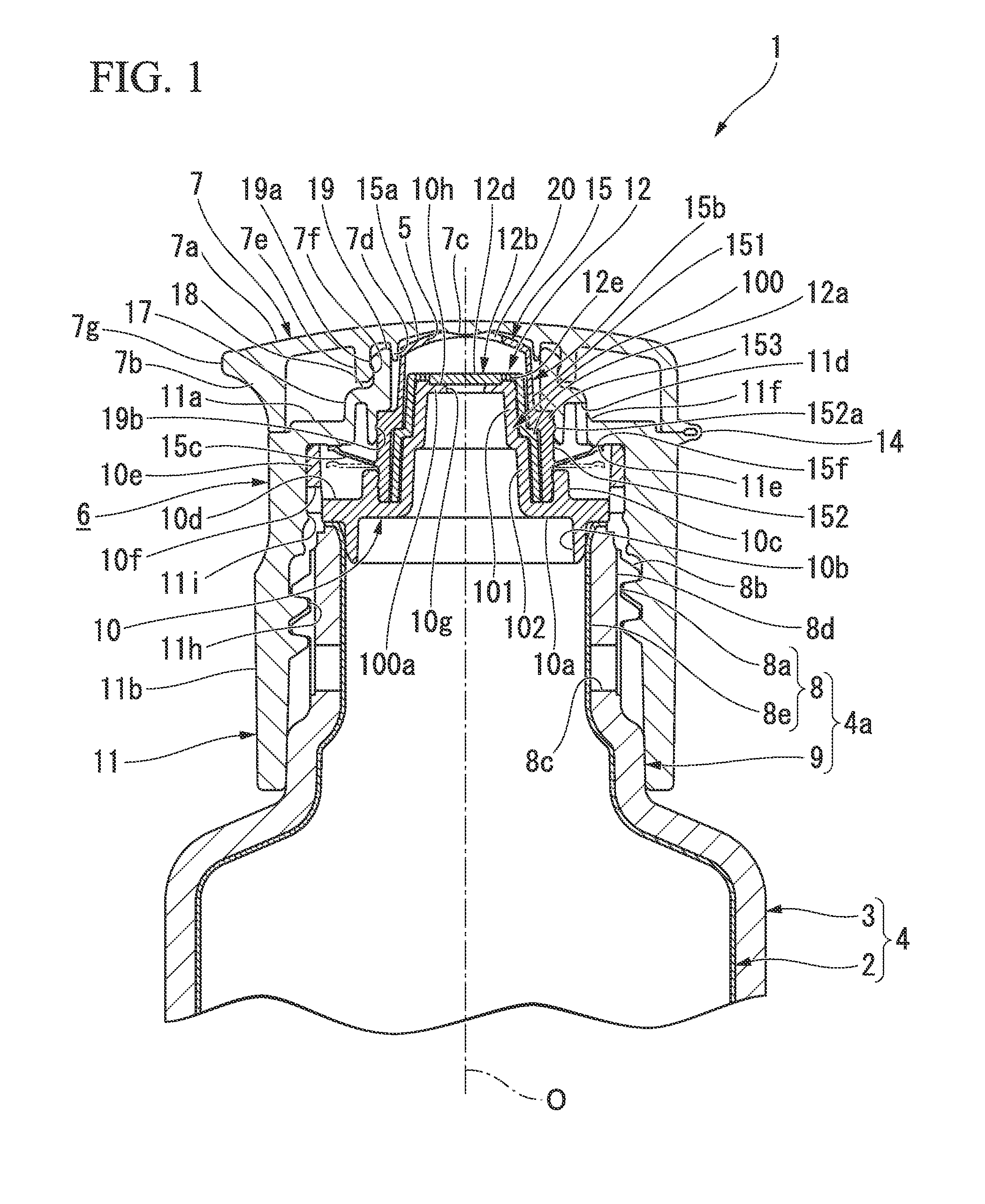
[0047]As shown in FIG. 1, a discharge container 1 includes a container main body 4, a discharge cap 6, and an over cap 7. The container main body 4 includes an inner container 2 configured to accommodate contents and having flexibility to be deformed according to reduction of the contents, and an outer container 3 in which the inner container 2 is installed to be elastically deformed. The discharge cap 6 has a discharge port 5 mounted on a port section 4a of the container main body 4 and configured to discharge the contents. The over cap 7 is detachably mounted on the discharge cap 6.

[0048]The container main body 4 is formed in a tubular shape having a bottom section, and the over cap 7 is formed in a tubular shape having a top section. Central axes of the container main body 4 and the over cap 7 are disposed on a common axis...

second embodiment

[0087]Hereinafter, a second embodiment of the present invention will be described with reference to the accompanying drawings.

[0088]FIG. 5 is a general partial cutaway view showing a state in which a lid section (an over cap) 216 of a discharge container 200 according to the embodiment is closed. As shown in FIG. 6, a container body (a container main body) 201 has an outer layer (an outer container) 202 and an inner layer (an inner container) 203. The container body 201 is blow-formed and configured as a delamination bottle-type container. The outer layer 202 is formed of a low density polyethylene material and has flexibility by which it can be squeezed and deformed so as to be easily recoverable. The inner layer 203 is formed of nylon and separably stacked on the outer layer 202. In addition, the inner layer 203 is formed in a pocket shape configured to accommodate the viscous contents N and to be freely deformed to reduce the volume as the pressure inside the container body 201 d...


PUM


Abstract

A discharge container includes a container main body having an inner container and an outer container, and a discharge cap, a suction hole configured to suction external air to a space between the inner container and the outer container is formed in the outer container, the discharge cap includes an air valve configured to switch between allowing and blocking communication between the outside of the discharge cap and the suction hole, and a discharge film elastically deformable to close the discharge port, and a slit is formed in the discharge film. As the discharge film is elastically deformed according to an increase in the pressure inside the inner container, the slit is widened and opened to open the discharge port.

Description

TECHNICAL FIELD[0001]The present invention relates to a discharge container. In particular, the present invention relates to a discharge container constituted by a container main body in which an inner container configured to form a volume-reducible inner package is stacked and formed to be separable in an outer container configured to form an outer shell, and a discharge cap assembled to a port section of the container main body.[0002]Priority is claimed on Japanese Patent Application Nos. 2011-238557, filed Oct. 31, 2011, and 2011-260052, filed Nov. 29, 2011, the contents of which are incorporated herein by reference.BACKGROUND ART[0003]In the related art, for example, as disclosed in Patent Document 1, a discharge container including a container main body having an inner container in which contents are accommodated and abundant flexibility to be deformed according to reduction in an accommodation amount of the contents and an outer container in which the inner container is instal...

Claims


Application Information

Patent Timeline
Patent Type & Authority Applications(United States)
IPC IPC(8): B65D77/06
CPCB65D77/06B65D83/0055B65D47/2031B65D51/1644B65D47/32
Inventor FURUSAWA, MITSUOHOSHINO, SHINYAIIZUKA, SHIGEO
Owner YOSHINO KOGYOSHO CO LTD
Why Eureka
Try Eureka