Transponder with tamper protection

a transponder and protection technology, applied in the field of radiofrequency transponders, can solve the problem of difficult removal of the device withou

Inactive Publication Date: 2014-09-18
SMARTRAC INVESTMENT BV
View PDF0 Cites 72 Cited by
  • Summary
  • Abstract
  • Description
  • Claims
  • Application Information

AI Technical Summary

Benefits of technology

[0024]According to an embodiment, the care label comprises an indication for cutting away said transponder, said indication positioned so that when said care label is cut along said indication, said tamper-protection loop is cut and the electrical conductivity of said tamper-protection loop is broken. According to an embodiment, the care comprises a perforation such that said care label can be torn along said indication, breaking the tamper-protection element. According to an embodiment, wherein said tamper-protection element is mounted on the care label in a removable manner so that said tamper-protection element can be removed by hand. According to an embodiment, the care label comprises a hard substrate or protective layer in the area of said antenna and said chip such that said hard substrate or protective layer is arranged to prevent breaking said antenna or said chip by cutting or tearing.
[0025]According to an eleventh aspect there is provided a care label for a garment, said care label comprising a radio-frequency identification transponder, said transponder comprising a chip, an antenna, and a tamper-detection element, said care label comprising a hard substrate or protective layer in the area of said antenna and said chip such that said hard substrate or protective layer is arranged to prevent breaking said antenna or said chip by cutting or tearing.

Problems solved by technology

This makes removing the device difficult without breaking the tamper detection element, and thereby shoplifting attempts can be more reliably noticed.

Method used


Image

  • Transponder with tamper protection
  • Transponder with tamper protection
  • Transponder with tamper protection

Examples


Embodiment Construction

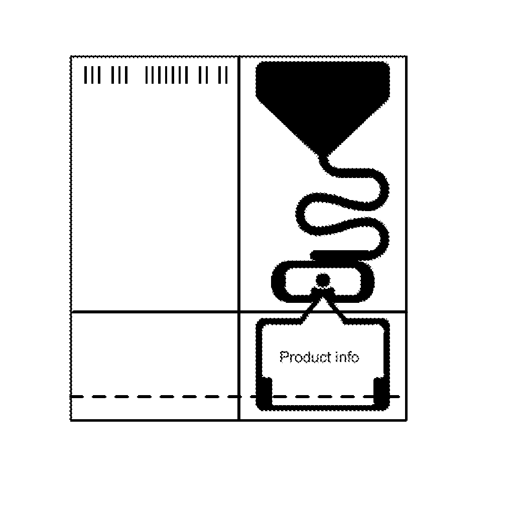
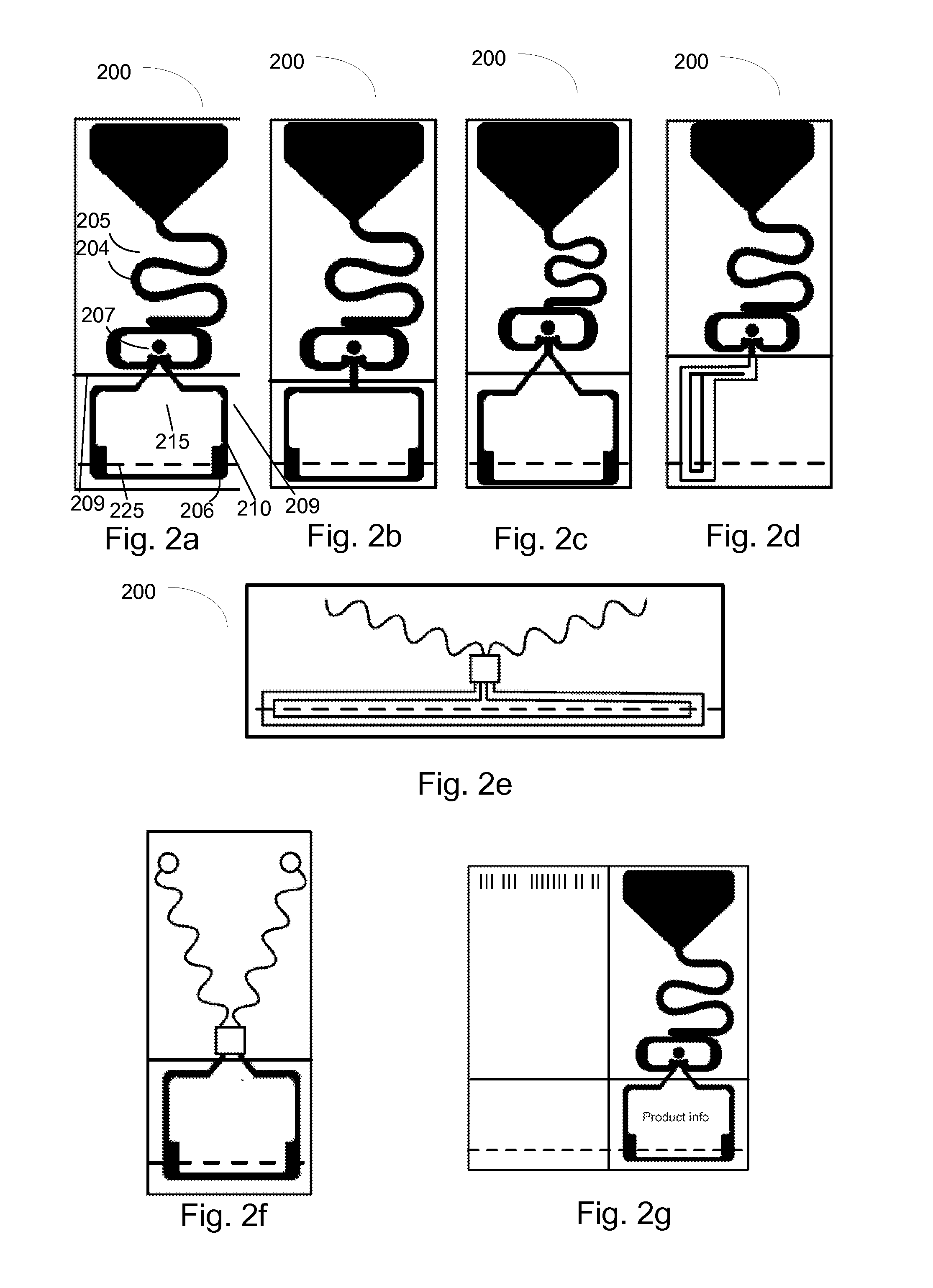
[0043]In the following, several embodiments of the invention will be described in the context of radio frequency identification (RFID) tags. It is to be noted, however, that the invention is not limited to RFID tags and systems only. Some examples are directed towards theft protection of garments, and the invention is not to be understood to be limited to such purposes. In fact, the different embodiments have applications widely in any environment where improved theft protection capabilities are needed.

[0044]Over time, the needs of having various kinds of information available on a product outgrew the capabilities of a simple bar code. To this end, new technologies were developed, such as two-dimensional bar codes. Of such technologies, radio frequency identification (RFID) has rather quickly become the technology of choice for identifying and tracking items. RFID technology has a vast number of applications making use of the ability to read an RFID tag from a distance even without ...


PUM


Abstract

The invention relates to sewable tamper detection elements for radio frequency identification devices, and to radio frequency identification devices with such tamper detection elements. The devices can be sewn into a seam of a garment so that the tamper detection element is partially inside the garment, e.g. as part of a care label. This makes removing the device difficult without breaking the tamper detection element, and thereby shoplifting attempts can be more reliably noticed. For this purpose, the tamper detection element is formed so that sewing through it does not break the element. The radio frequency identification device may be formed asymmetric so that the tamper detection element is on a different side from the antenna elements with respect to the chip. In this manner, the disturbance from the tamper detection element to the antenna can be minimized. The tamper detection element may be formed so that it contains a transparent opening on which text can be printed.

Description

FIELD OF THE INVENTION[0001]The present invention relates to radio-frequency transponders and elements for such transponders that have a tamper-protection means, as well as to systems and methods for the same.BACKGROUND OF THE INVENTION[0002]RFID (Radio Frequency Identification) transponders are utilized in consumer products to identify such a product among other products but also to give information on the product. An RFID transponder can be attached to the product, such as a clothing, a book, an electronic device, etc. Traditionally RFID transponders have been attached to the product as adhesive tags or as hang tags and used mostly for logistic purposes. RFID transponders can also be used for preventing shoplifting (to be used in parallel or to replace current electronic article surveillance components). In such applications, the RFID transponder may be hidden into the product or attached to the product in such way that it cannot be removed without breaking the transponder and the...

Claims


Application Information

Patent Timeline
Patent Type & Authority Applications(United States)
IPC IPC(8): G06K19/077
CPCG06K19/07798D06H1/04G06K19/07372G09F3/0297G09F2003/0282G08B13/2417G08B13/2431G08B13/2434G08B13/2448G06K19/027G06K19/07381
Inventor KERVINEN, KIRSIKOIVISTO, TEROKOSKELAINEN, TUOMAS
Owner SMARTRAC INVESTMENT BV
Why Eureka
Try Eureka