Self-Regulating Irrigation Controller

a self-regulating, controller technology, applied in watering devices, horticulture, agriculture, etc., can solve the problems of reducing limiting the flow of water, and closing the irrigation system, so as to reduce the expansion of the membrane, appropriately calibrate the irrigation system, and limit the flow of water.

Inactive Publication Date: 2014-09-18
SHIELDS RODNEY M
View PDF3 Cites 0 Cited by
  • Summary
  • Abstract
  • Description
  • Claims
  • Application Information

AI Technical Summary

Benefits of technology

The invention uses a special membrane that expands in wet conditions to control the movement of water. When this membrane reaches its maximum size, it closes off the opening, preventing more water from coming through. To adjust how much water flows through, there's a collar-like device called an adjustment collar that tightens or loosens the membrane. Turning the collar makes the membrane smaller or larger, depending on what kind of pressure needs to be created.

Problems solved by technology

The technical problem addressed in this patent text is the need for a more efficient and cost-effective way to regulate plant growth through irrigation systems. Current systems require manual calibration and can be affected by external factors such as rain water, leading to decreased efficiency. The patent proposes a solution that regulates flow according to the actual amount of moisture present in the environment, with minimal or no human monitoring and without the need for expensive, complicated, and power-consuming electronic components.

Method used


Image

  • Self-Regulating Irrigation Controller
  • Self-Regulating Irrigation Controller
  • Self-Regulating Irrigation Controller

Examples


embodiment

Cam Locking Embodiment

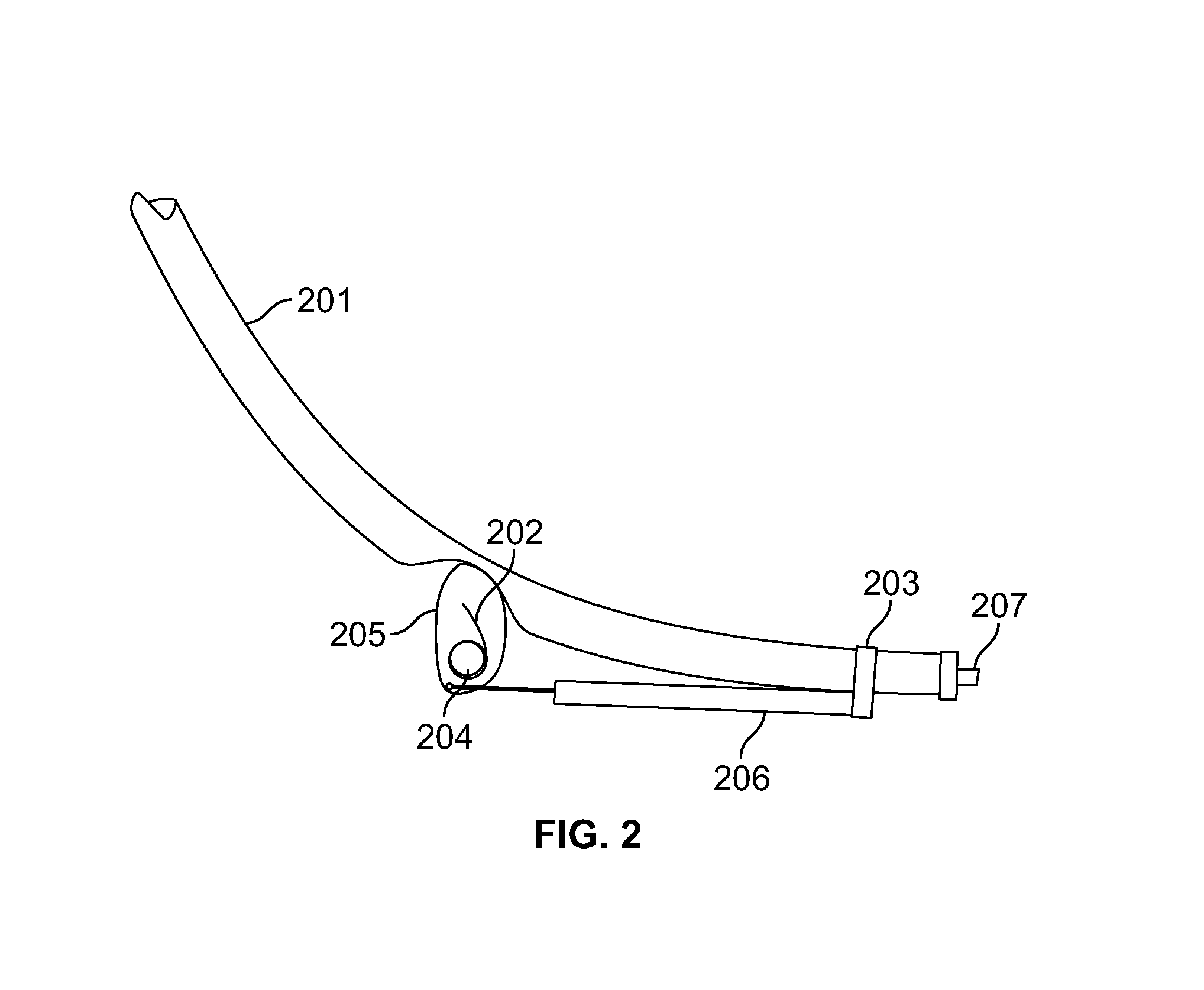
[0022]A second embodiment of the irrigation control system uses a cam locking mechanism. This mechanism is outlined in FIG. 2. The control valve in this embodiment is an elastic tube [201]. Using a clip or fastener [203] the elastic tube [201] is joined to a hydro-expansive membrane [206]. The hydro-expansive membrane [206] is attached to a cam [205]. This attachment can take many forms including a rod, gears, string, cable, or the like. If the attachment is flexible (e.g., a cable), the irrigation control system will include a control spring [202] that applies force on the cam [205] in opposition to force applied by the hydro-expansive membrane [206]. The cam [205] is placed on a pivot [204] near the elastic tube [201]. The elastic tube [201] can be attached to a spout [207], sprinkler head, or similar watering apparatus.

[0023]In moist environments the hydro-expansive membrane [206] will expand. This expansion will rotate the cam [205] so that it deforms the e...


PUM


Abstract

A self-regulating irrigation system utilizing a hydro-expansive material to regulate fluid flow. an irrigation control valve that includes (i) a sprinkler with a control valve, wherein said control valve comprises a control spring and a diaphragm located within the sprinkler head, (ii) a base extending down from said sprinkler head, and (iii) a hydro-expansive control membrane attached to the diaphragm and the base. The hydro-expansive control membrane is a length of hydro-expansive material that is short enough and strong enough to overcome the force of the control spring when the control membrane is dry, yet long enough that it will extend when wet so that the force of the control spring overcomes the force of the control membrane to close the diaphragm.

Description


Claims


Application Information

Patent Timeline
Owner SHIELDS RODNEY M
Why Eureka
Try Eureka