Steering knuckle

a steering knuckle and knuckle technology, applied in the field of aftermarket vehicles, can solve problems such as negative effects on vehicle performance and handling, and achieve the effects of reducing the relative angle of the upper control arm, improving characteristics, and high performance handling

Inactive Publication Date: 2014-09-18
KW AUTOMOTIVE NORTH AMERICA
View PDF3 Cites 11 Cited by
  • Summary
  • Abstract
  • Description
  • Claims
  • Application Information

AI Technical Summary

Benefits of technology

[0008]The improved vehicle lowering steering knuckles of the present invention are superior to existing vehicle lowering steering knuckles because they are capable of lowering a vehicle while maintaining or improving vehicle handling, increasing caster, and improving alignment capabilities. Among other things, the vehicle lowering steering knuckles of the present invention improve handling characteristics by adding caster angle (an additional degree of caster) into the steering knuckle, allowing the original caster specifications to be increased without changing the forward or aft locations of the vehicle wheels. This is achieved by adjusting the mounting location of the upper ball joint laterally or horizontally so that the mounting points are adjusted without affecting the front wheel placement. In addition, in embodiments of the present invention, the downward angle of the upper ball joint mount is increased, thereby allowing for additional lowering of the vehicle chassis, especially when used in conjunction with an adjustable shock or strut, such as that disclosed in U.S. Pat. No. 8,070,171.

Problems solved by technology

This movement of the upper ball joint necessarily results in moving the location of the vehicle wheels, which can negatively affect vehicle performance and handling.

Method used


Image

  • Steering knuckle
  • Steering knuckle
  • Steering knuckle

Examples


Embodiment Construction

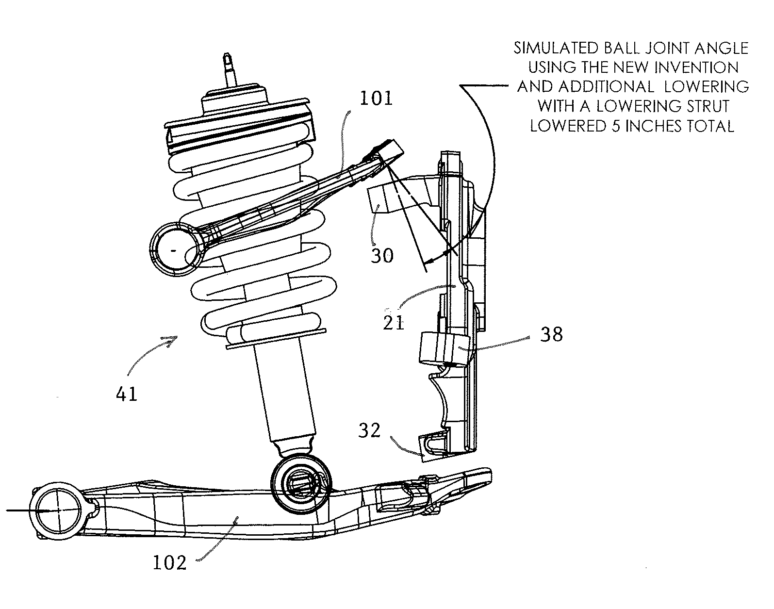
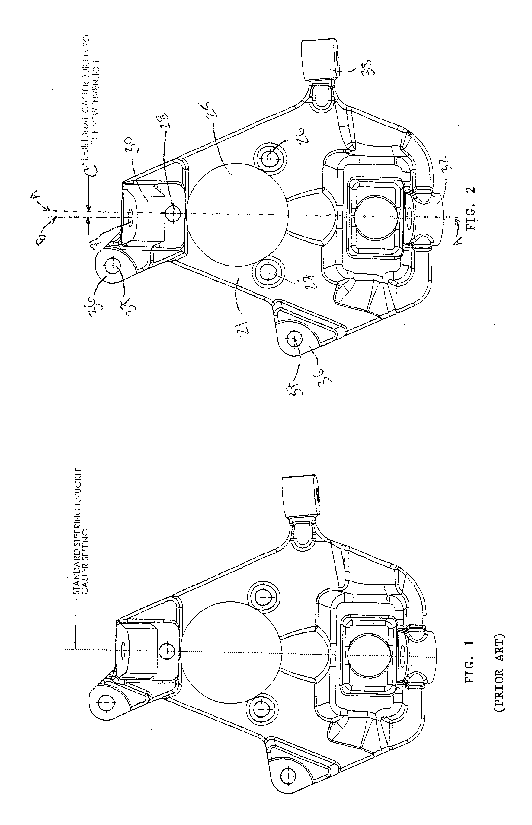
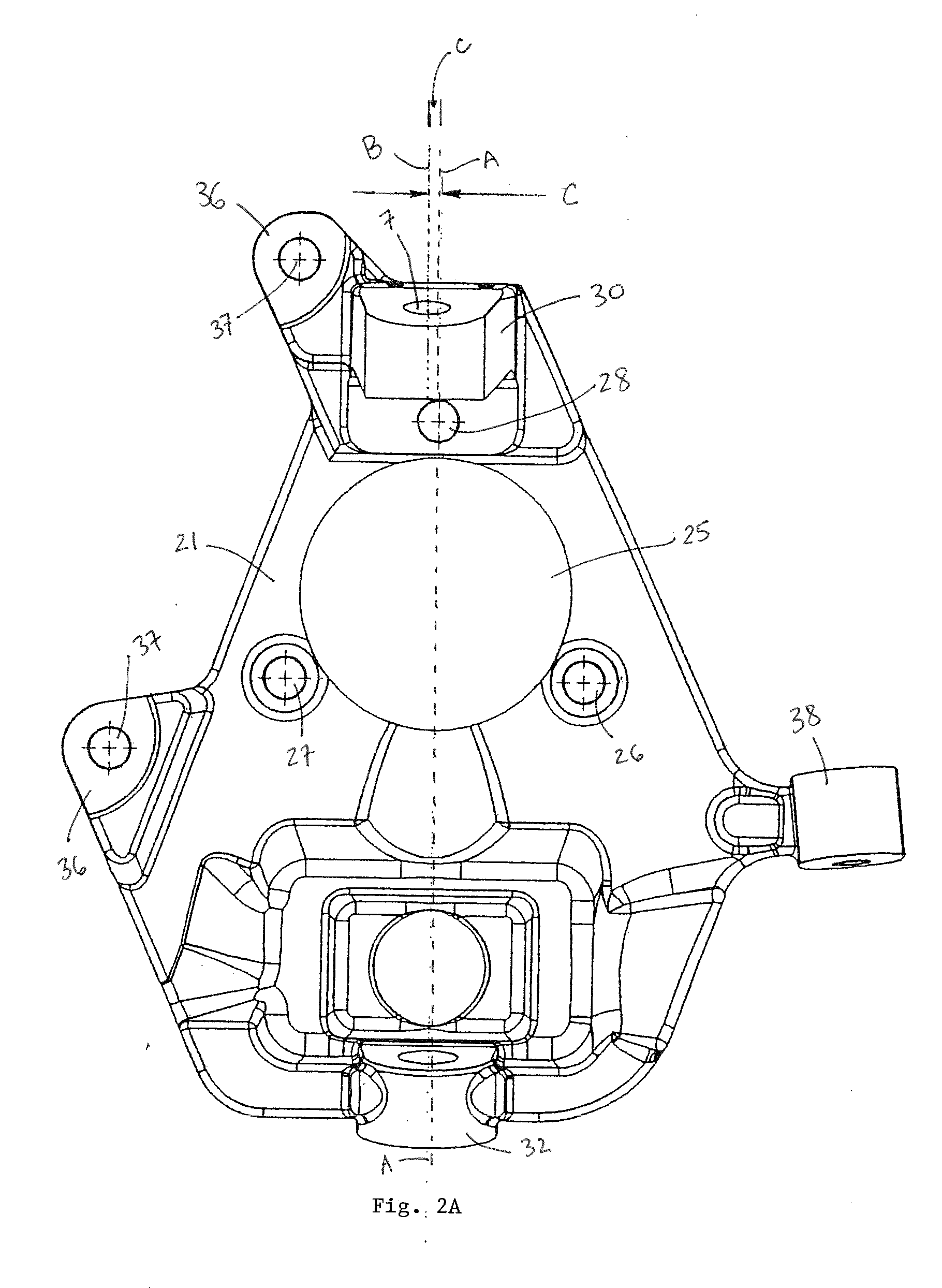
[0028]Referring to the drawings wherein like reference characters designate like or corresponding parts throughout the several views, and referring particularly to FIGS. 2-4, it is seen that the illustrated embodiment of the present invention includes a steering knuckle having a cast body 21 with a large-diameter circular bore 25 centrally located therein for receiving a wheel hub assembly. The steering knuckle 21 includes three bolt openings 26, 27 and 28 for receiving corresponding bolt assemblies of the wheel hub. Referring to FIG. 2, it is seen that cast body 21 of the illustrated embodiment includes an upper ball joint mount 30, a lower ball joint mount 32, a steering arm attachment tab 38, and tabs 36 with openings 37 therein for attachment of the brake caliper to the steering knuckle body.

[0029]Referring to the side view of FIG. 2, it is seen that upper ball joint mount 30 is located at the top of the steering knuckle body 21, on the opposite side of bolt opening 28 from bore...


PUM


Abstract

The present invention provides improved aftermarket vehicle lowering steering knuckles that are superior to existing aftermarket steering knuckles because they are capable of lowering a vehicle while maintaining or improving vehicle handling, increasing caster, and improving alignment capabilities. Embodiments of the vehicle lowering steering knuckles of the present invention improve handling characteristics by adding caster angle into the steering knuckle, allowing the original caster specifications to be increased without changing the forward or aft locations of the vehicle wheels. This is achieved by adjusting the mounting location of the upper ball joint laterally so that the mounting points are adjusted without affecting the front wheel placement. Embodiments of the vehicle lowering steering knuckles of the present invention also increase vehicle lowering capacity by increasing the downward angle of the upper ball joint mount.

Description

BACKGROUND OF THE INVENTION[0001]1. Field of Invention The present invention relates to after-market vehicle-lowering steering knuckles (drop spindles), and more particularly to a newly designed drop spindle which provides improved handling characteristics, increased caster, and which allows a vehicle equipped with such a steering knuckle to be aligned for performance handling.[0002]2. Description of the Related Art[0003]A typical spindle (or steering knuckle) is a component of the front suspension of a vehicle, which attaches the wheel and brake assemblies to the vehicle, and allows the wheels to travel vertically (oust and rebound), turn, and rotate. The most common spindle bodies are of a cast metal configuration utilizing a metallic, machined, cylindrical shaft called a spindle pin to which the wheel bearings, brake components, and wheel are affixed. In particular, a wheel hub fits over the elongated spindle pin with bearing surfaces actually making contact with the pin. A vehic...

Claims


Application Information

Patent Timeline
Patent Type & Authority Applications(United States)
IPC IPC(8): B62D7/18
CPCB62D7/18B60G3/20B60G2204/148
Inventor BUNKER, ROBERT DANIELBRANDT, DALLAS WAYNEKOJIMA, MICHAEL K.
Owner KW AUTOMOTIVE NORTH AMERICA
Why Eureka
Try Eureka