Rear wheel toe angle control system for a vehicle

a control system and rear wheel technology, applied in the direction of underwater vessels, non-deflectable wheel steering, special data processing applications, etc., can solve the problems of changing the operating speed of the electric actuator, impairing the impression of etc., and achieve the effect of improving the handling of the vehicl

Active Publication Date: 2014-06-17
HONDA MOTOR CO LTD
View PDF36 Cites 4 Cited by
  • Summary
  • Abstract
  • Description
  • Claims
  • Application Information

AI Technical Summary

Benefits of technology

[0016]According to the present invention, the toe angle response properties of the right and left wheels are prevented from differing from each other depending on the operating condition of the vehicle, and the handling of the vehicle can be improved.

Problems solved by technology

However, as the operating condition of the vehicle and / or the loading of the vehicle change, because the axial force that is applied to the electric actuator changes in a corresponding manner, the torque of the motor that is required to achieve a prescribed displacement changes, and this causes a change in the operating speed of the electric actuator.
In other words, there may be some difference in the toe angle response between the two rear wheels, and this may impair the impression of the handling of the vehicle.

Method used


Image

  • Rear wheel toe angle control system for a vehicle
  • Rear wheel toe angle control system for a vehicle
  • Rear wheel toe angle control system for a vehicle

Examples


Embodiment Construction

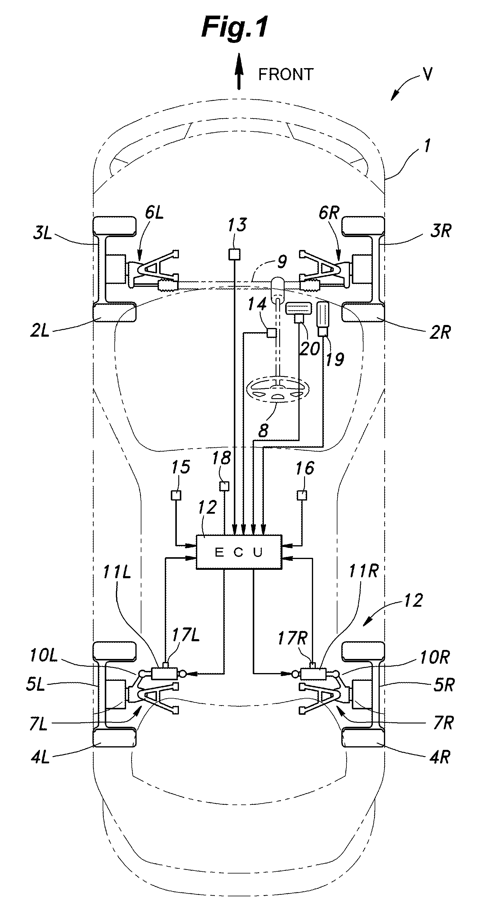
[0026]A vehicle V incorporated with a rear wheel toe angle control system embodying the present invention is described in the following with reference to the drawings. In the following description, each wheel and the parts associated therewith such as a tire and an electric actuator are denoted with a numeral followed by a suffix L or R depending on which side of the vehicle body the relevant part is located. For instance, the rear wheels are indicated as a rear wheel 5L (left wheel) and a rear wheel 5R (right wheel), and are also collectively indicated as rear wheels 5.

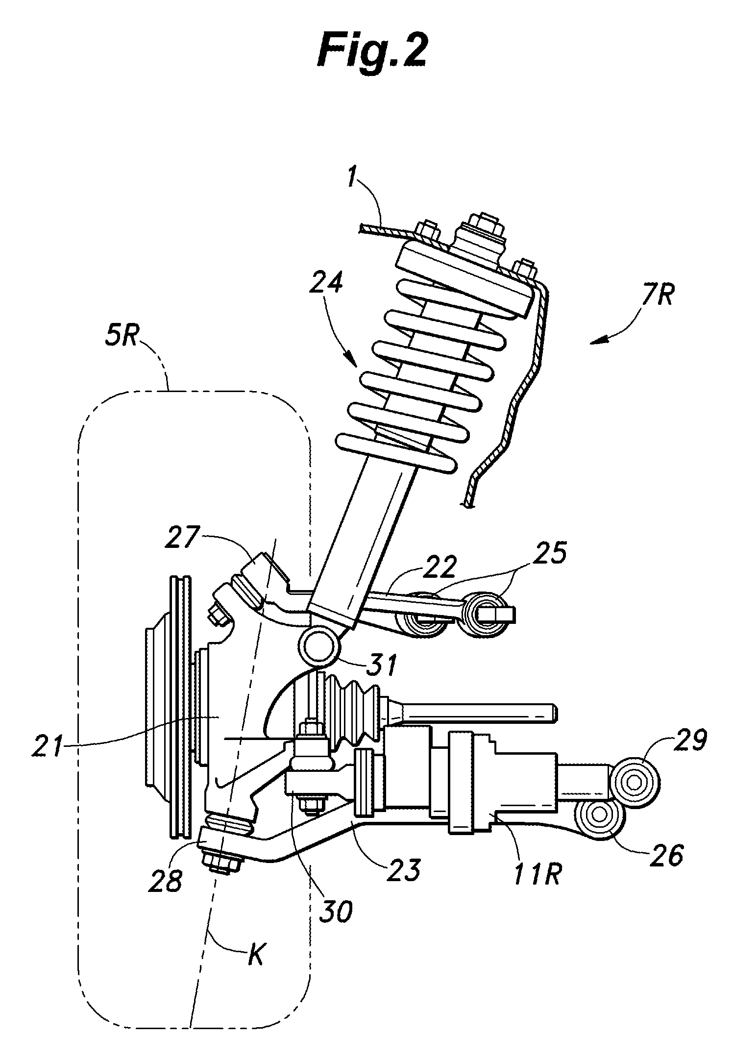
[0027]As shown in FIG. 1, the vehicle V consists of a four wheel automobile including a pair of front wheels 3L and 3R each fitted with a tire 2L, 2R, and a pair of rear wheels 5L and 5R each fitted with a tire 4L, 4R, and these wheels are supported by the vehicle body 1 via corresponding front suspension systems 6L and 6R and corresponding rear suspension systems 7L and 7R, respectively.

[0028]The vehicle V further c...


PUM


Abstract

In a rear wheel toe angle control system, the toe angle response properties of the right and left wheels are prevented from differing from each other depending on the operating condition of the vehicle, and the handling of the vehicle can be improved. The rear wheel toe angle control system (10) comprises a control command angle computing unit (83) for setting a target toe angel for each rear wheel (5) according to an operating condition of the vehicle (V), an angle-length conversion unit (87) for setting a target operating amount of each electric actuator (11) according to the target toe angle, a stroke sensor (17) for detecting an actual operating amount of each electric actuator (11), a motor position feed back duty computation unit (89) for setting a control value of each electric actuator (11) according to the difference between the actual operating amount and the target operating amount, and a compensating unit (90) for compensating the control value according to a value such as the lateral acceleration of the vehicle body (1) which is associated with the axial force of each electric actuator (11).

Description

TECHNICAL FIELD[0001]The present invention relates to a rear wheel toe angle control system for a vehicle for individually varying toe angles of rear wheels of the vehicle, and in particular to a technology for preventing the response properties of the right and left toe angles depending on operating conditions of the vehicle.BACKGROUND OF THE INVENTION[0002]In recent year, development efforts are directed to four wheel steering vehicles equipped with a rear wheel toe angle control system for variably controlling the rear wheel toe angles with the aim of improving the yaw response of the vehicle and the driving stability of the vehicle. In a known rear wheel toe angle control system, an electric actuator is provided in a connecting part between a lateral link or a trailing link of each rear wheel suspension system and the vehicle body such that the toe angles of the rear wheels can be individually varied by appropriately driving the electric actuators. See Patent Document 1, for ins...

Claims


Application Information

Patent Timeline
Patent Type & Authority Patents(United States)
IPC IPC(8): B62D17/00B62D6/00B60G7/00B62D7/15B62D7/14B62D5/04
CPCB62D5/0418B60G7/006B62D7/146B60G2200/462B62D17/00B60G2202/422B62D7/159
Inventor AOKI, YOSHIMASATANAKA, KUNIYOSHI
Owner HONDA MOTOR CO LTD
Why Eureka
Try Eureka