Gearbox Mounting System

a technology for mounting systems and gearboxes, applied in the direction of gearing, jet propulsion mounting, transportation and packaging, etc., can solve the problems of affecting the handling of vehicles at will, and achieve the effect of increasing the torsional rigidity of the vehicle, being economical and easily adaptabl

Active Publication Date: 2019-05-02
AUTO IP LLC
View PDF0 Cites 2 Cited by
  • Summary
  • Abstract
  • Description
  • Claims
  • Application Information

AI Technical Summary

Benefits of technology

[0005]The present invention provides a system for mounting a gearbox in a vehicle that is both economical and easily adaptable to a wide number of vehicle constructions, including ladder-chassis, exoskeleton / space frame and others. The present invention not only strongly secures the gearbox (and the engine) to the vehicle, but beneficially contributes to increased vehicle torsional rigidity.

Problems solved by technology

In automotive vehicles using for example internal combustion engines, an increase or decrease in crankshaft speed and engine torque can cause the engine to twist in its mounts, which can in turn twist the vehicle structure itself, thereby deleteriously impacting vehicle handling.

Method used


Image

  • Gearbox Mounting System
  • Gearbox Mounting System
  • Gearbox Mounting System

Examples


Embodiment Construction

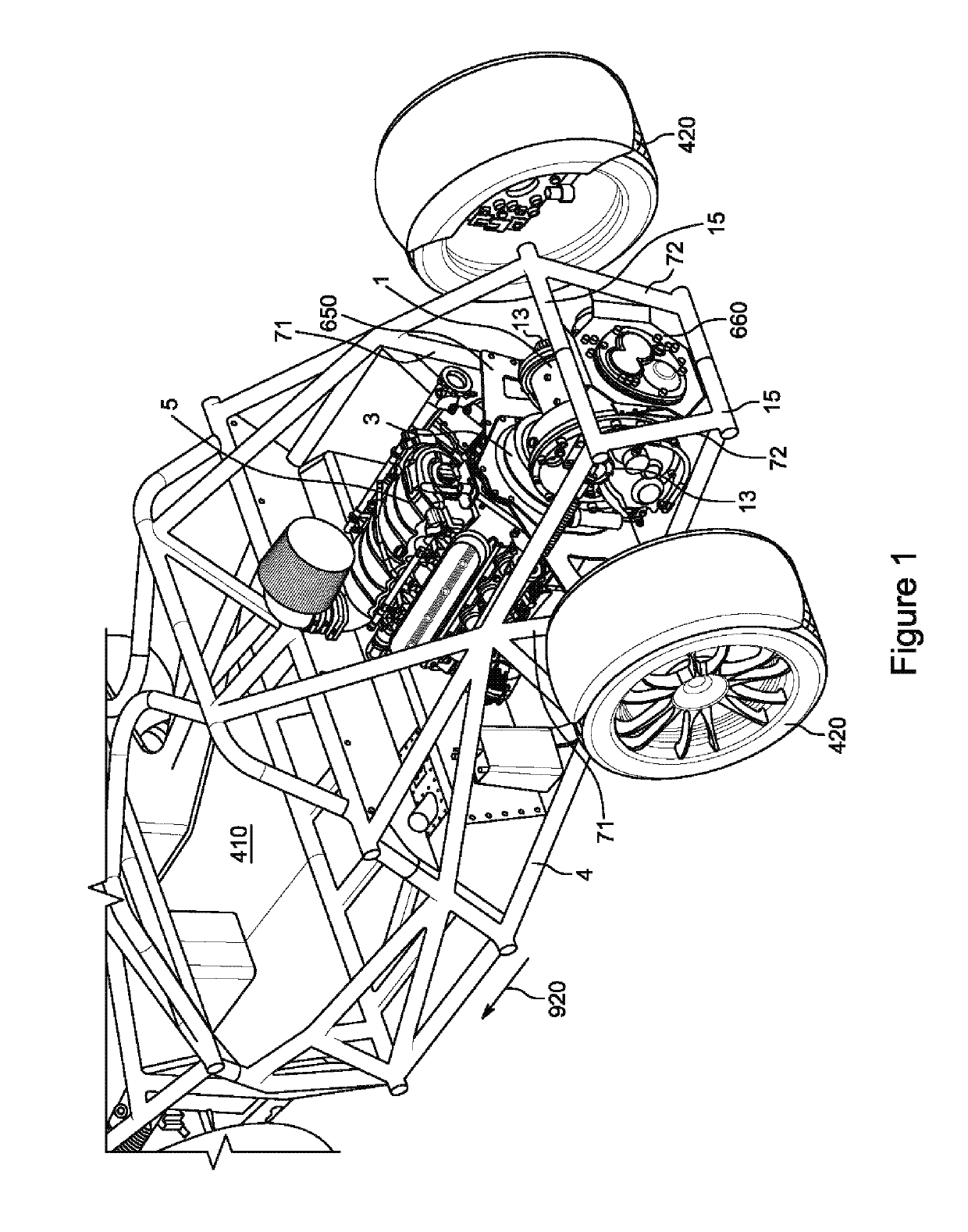
[0020]In the embodiment of the present invention depicted in FIG. 1, there is shown a vehicle 4 having an engine 5, a clutch housing 3 and a gearbox 1. Vehicle 4 is a four-wheeled vehicle, with rear wheels 420 shown in FIG. 1, and with the two front wheels of vehicle 4 omitted for clarity. Gearbox 1 as shown in FIG. 1 is a transaxle design, integrating in one housing both primary engine gearing and the gearing used to differentially rotate the driving wheels. Vehicle 4 as shown is a mid-engine, rear wheel drive configuration with the engine 5 located to the rear of the passenger compartment 410 and ahead of the rear axle, and with the gearbox 1 mounted rearward of the engine 5. The output shafts 13 of gearbox 1, which in the embodiment of FIG. 1 are approximately oriented in the horizontal plane, are connected to two axle shafts (not shown), to rotate rear wheels 420 and propel the vehicle.

[0021]In this disclosure, the direction of vehicle forward travel is indicated by arrow 920, s...


PUM


Abstract

A combination of an engine, a gearbox clutch housing and a mounting system for mounting the combination to the structural load-bearing components of a vehicle, comprising an engine having a first contact surface; a gearbox clutch housing having a second contact surface, the first contact surface of the engine and the second contact surface of the gearbox clutch housing each being joined to the other by mechanical fastening means; and a first hanger, where the latter comprises a rigid plate positioned between the first contact surface of the engine and the second contact surface of the gearbox clutch housing, with the first hanger being securely fastened between the engine and the gearbox clutch housing. The first hanger has first and second opposed load-transferring surfaces of closed perimeter, with the first of the load-transferring surfaces being in pressing contact with the first contact surface of the engine and the second of the load-transferring surfaces being in pressing contact with the second contact surface of the gearbox clutch housing. The first hanger includes one or more load-supporting members extending beyond the perimeter of the opposed load-transferring surfaces; and the one or more load-supporting members include plural spaced-apart fastening elements adapted for coupling to one or more select structural load-bearing components of a vehicle.

Description

CROSS-REFERENCES TO RELATED APPLICATIONS[0001]This application claims the benefit of U.S. Provisional Application No. 62 / 577,423, filed Oct. 26, 2017, U.S. Provisional Application No. 62 / 577,965, filed Oct. 27, 2017, U.S. Provisional Application No. 62 / 616,601, filed Jan. 12, 2018 and U.S. Provisional Application No. 62 / 735,966, filed Sep. 25, 2018.BACKGROUND OF THE INVENTIONField of the Invention[0002]This invention relates to systems for securing a gearbox to the structural portions of a vehicle.Description of the Related Art[0003]Gear systems are used in order to better match the torque, power and rotational speed characteristics of a rotating power source with the needs of the application. In the case of gearboxes used in connection with internal combustion engines for automotive applications, current designs may employ a 3-point system for mounting the gearbox and engine in the vehicle. For example, for a front engine, rear wheel drive vehicle, the engine may be secured to the ...

Claims


Application Information

Patent Timeline
Patent Type & Authority Applications(United States)
IPC IPC(8): F16H57/025B60K17/08
CPCF16H57/025F16H2057/0203B60K17/08B60K17/06B60K2005/003F16H57/0441F16H57/031F16H2057/0235F16H2057/02043F16H3/089F16H61/0025
Inventor TIRAMANI, PAOLODENMAN, KYLE
Owner AUTO IP LLC
Why Eureka
Try Eureka