Handlebar arrangement

a handlebar arrangement and handlebar technology, applied in the field of vehicles, can solve the problems of not providing for the movement of the handlebar generally closer, the rider still having to lean generally forward, and the rider being uncomfortable and off balance, etc., and achieves the effect of full steering control of the vehicle, convenient use, and low manufacturing cos

Inactive Publication Date: 2013-08-01
WONG JON
View PDF17 Cites 4 Cited by
  • Summary
  • Abstract
  • Description
  • Claims
  • Application Information

AI Technical Summary

Benefits of technology

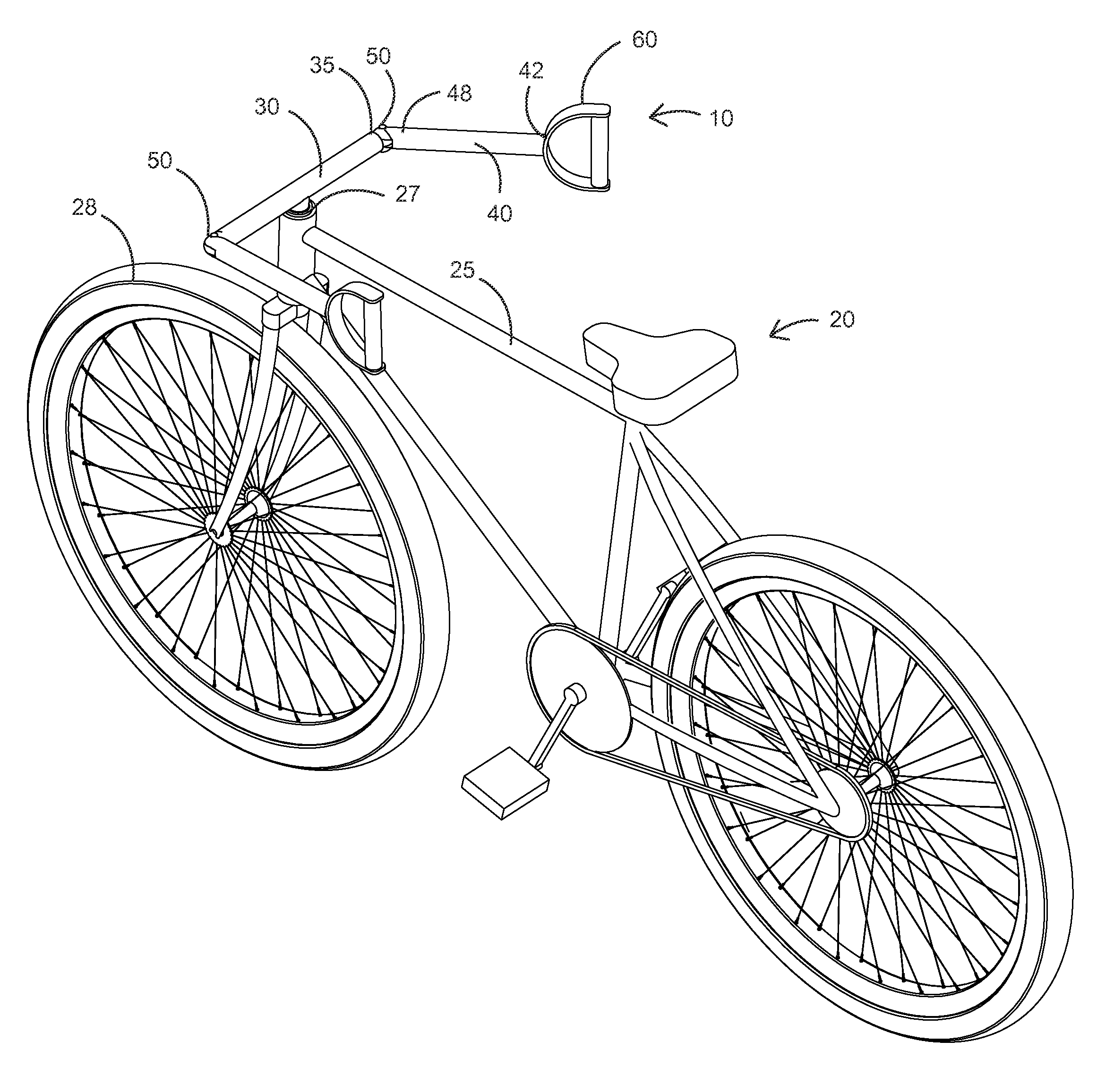
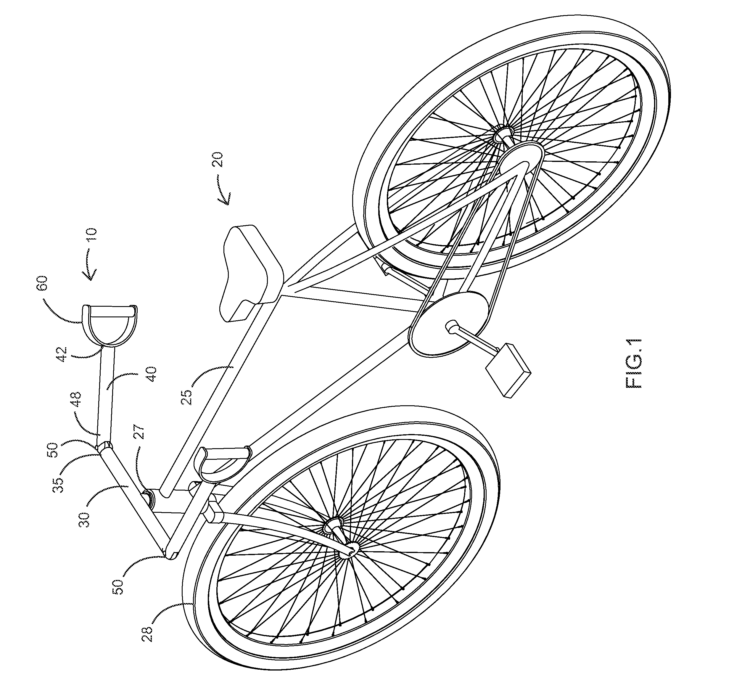
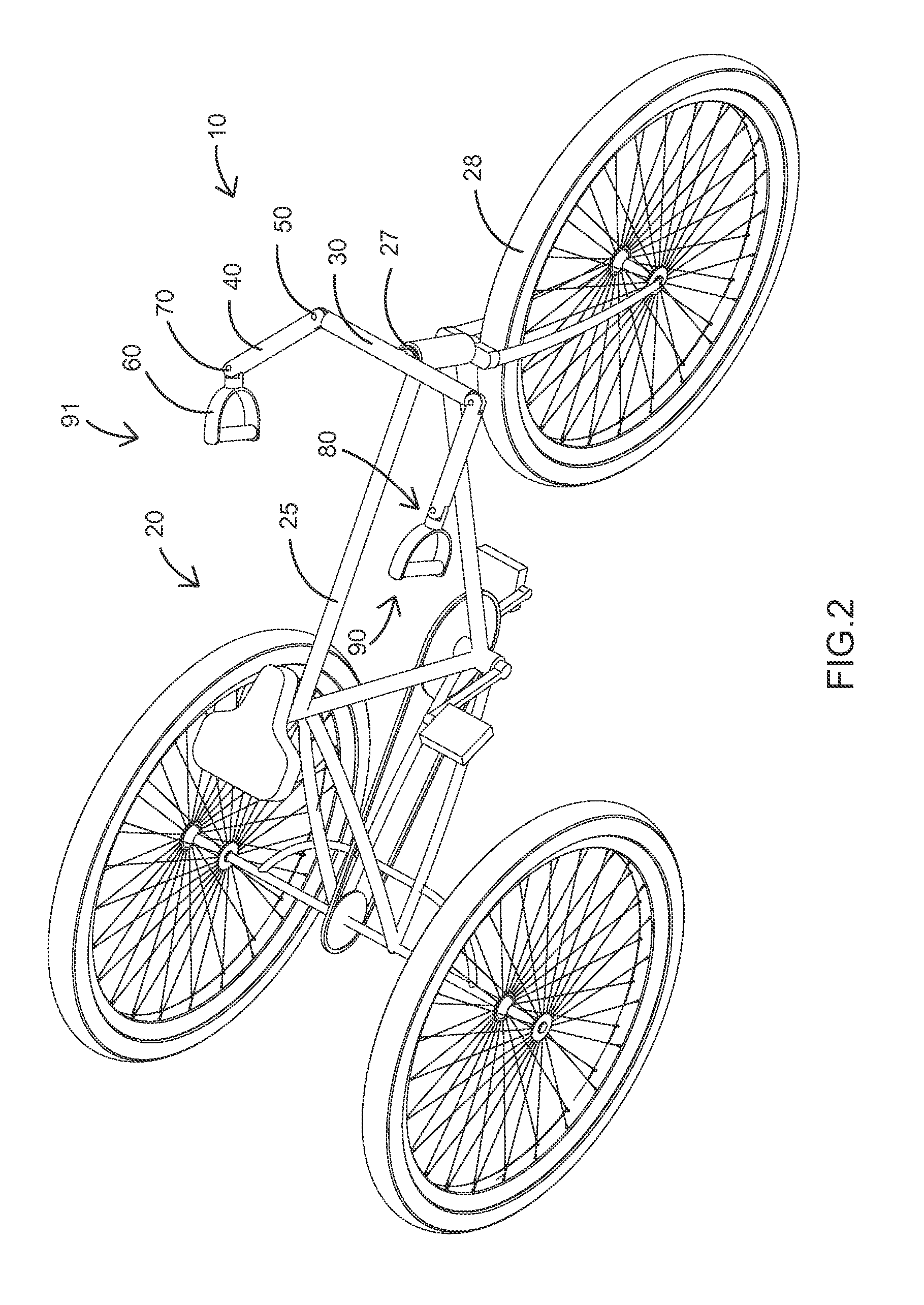
[0014]The present invention is a handlebar arrangement that allows the rider to sit-up straight or even recline without leaning forward, all while maintaining full steering control of the vehicle. The present device allows for a wide variety of adjustments and positions of the handles that ultimately steer the vehicle's front wheel, as dictated by comfort of the rider. Moreover, the present device is relatively inexpensive to manufacture and easy to use. The connecting rod embodiments stabilize the handles and tie rods with respect to each other, and allows for one-handed steering of the vehicle. The multiple pivoting system of the present invention allows steering in a more fore and aft arm motion, allowing the rider to stay more centralized over the seat, more comfortable, and more stable.
[0015]Each handle can be operated at a different distance from the first pivot as desired by the rider. The present system allows for a decreased turn radius with the user being able to maintain a more centered position on the vehicle. Further, lengthening the distance between the first pivot and the handles allows for retention of a more vertically-oriented first pivot, which improves handling of the vehicle (unlike a more “chopper” style inclined first pivot which also moves the handlebars backwards more towards the user but results in degraded handling). The present device reduces a rider's stress and fatigue that prior art arrangements caused by requiring a substantially stationary holding position of the handle and a fixed, repetitious path of the hands and arms for steering. The multi-pivoting functions and movements mimic the human body (arms, joints, and tendons) and becomes in no small part a more natural, fluid, and intuitive extension of the user's body. Other features and advantages of the present invention will become apparent from the following more detailed description, taken in conjunction with the accompanying drawings, which illustrate, by way of example, the principles of the invention.

Problems solved by technology

This can be uncomfortable, particularly during extended rides.
Such a device, however, doesn't provide for moving the handlebars generally closer to the rider, resulting in the rider still having to lean generally forward while steering.
If the U-shaped ends were enlarged, rotating could move the handlebars closer to the rider, but with only a single pivot about a vertical axis on the handlebars the handlebar swing radius is enlarged, causing the rider to swing outward further along with the center of gravity, which makes the rider both uncomfortable and off balance.
Just extending the handlebars rearwardly, as suggested by U.S. Pat. No. 379,955 to Hedger on Mar. 27, 1888, and as shown in U.S. Pat. No. 619,126 to Blashfield on Feb. 7, 1899, is a poor solution since the effective range of the steering with such a handle will be limited to the reach of the rider's arms along an arc defined by the length of the handlebars from the first pivot point.
Further, such handlebars if lengthened sufficiently impact the rider with only a small turn of the handlebars, restricting the rotational range of the handlebars and very possibly dangerously so.
Such a device does not allow the continuous rotational adjustment of the handlebar ends nor does it provide for much extension of the handlebars rearwardly towards the driver.
Generally, prior art devices such as Kochera with adjustable handlebars teach the ends of the handlebars being vertically adjustable up and down, which does little to help a rider keep a more vertical position over the seat and center of gravity of the vehicle.
This results in additional fatigue and discomfort.

Method used


Image

  • Handlebar arrangement
  • Handlebar arrangement
  • Handlebar arrangement

Examples


Embodiment Construction

[0033]Illustrative embodiments of the invention are described below. The following explanation provides specific details for a thorough understanding of and enabling description for these embodiments. One skilled in the art will understand that the invention may be practiced without such details. In other instances, well-known structures and functions have not been shown or described in detail to avoid unnecessarily obscuring the description of the embodiments.

[0034]Unless the context clearly requires otherwise, throughout the description and the claims, the words “comprise,”“comprising,” and the like are to be construed in an inclusive sense as opposed to an exclusive or exhaustive sense; that is to say, in the sense of “including, but not limited to.” Words using the singular or plural number also include the plural or singular number respectively. Additionally, the words “herein,”“above,”“below” and words of similar import, when used in this application, shall refer to this appli...


PUM


Abstract

A handlebar arrangement for a bicycle or the like includes a handlebar having two opposing sides and adapted to turn a front wheel at a first pivot. Two tie rods are each pivotally attached at a forward end thereof proximate one of the ends of the handlebar at one of a pair of second pivots. Each tie rod terminates at a handle. In different embodiments, each handle is pivotally attached to the rearward end of one of the tie rods, or the handle of each tie rod includes a rotational bearing where connected to the tie rod, or each tie rod is pivoted to allow substantially 180 degrees of horizontal pivoting of the tie rod with the handlebar, and substantially 90 degrees of vertical upward pivoting of the tie rod with the handlebar, or each tie rod may be mutually pivotally connected with a connecting rod.

Description

CROSS-REFERENCE TO RELATED APPLICATIONS[0001]This application claims the benefit of U.S. Provisional Patent Application 61 / 591,804, filed on Jan. 27, 2012, and incorporated herein by reference.STATEMENT REGARDING FEDERALLY SPONSORED RESEARCH AND DEVELOPMENT[0002]Not Applicable.FIELD OF THE INVENTION[0003]This invention relates to vehicles, and more particularly to an improved handlebar arrangement.BACKGROUND[0004]Traditional bicycle handlebars, and similar handlebars for other velocipede-type vehicles, pivot around a first pivot of the vehicle to steer the front wheel thereof. As such, a rider typically must lean well forward in order to reach both sides of the handlebar as it pivots around the first pivot. This can be uncomfortable, particularly during extended rides.[0005]Several prior art patents teach devices that aim to make such bicycle handlebars adjustable to accommodate different sized riders or to allow for more comfortable handlebar positioning. For example, U.S. Pat. No....

Claims


Application Information

Patent Timeline
Patent Type & Authority Applications(United States)
IPC IPC(8): B62K21/12
CPCY10T74/20828B62K21/12
Inventor WONG, JON
Owner WONG JON
Why Eureka
Try Eureka