Front suspension structure of automotive vehicle

a front suspension and automotive technology, applied in the direction of suspension arms, vehicle components, resilient suspensions, etc., can solve the problems of uneven movement vertically, difficulty in damper unit adjustment, and increase in the number of components or movable portions, so as to improve the road-following property, improve the handling stability of the vehicle, and improve the effect of riding conformability

Active Publication Date: 2020-02-11
MAZDA MOTOR CORP
View PDF19 Cites 3 Cited by
  • Summary
  • Abstract
  • Description
  • Claims
  • Application Information

AI Technical Summary

Benefits of technology

[0009]Accordingly, an object of the present invention is to provide a front suspension structure of an automotive vehicle which can compatibly attaining the improvement of the vehicle handling stability for controlling the wheel with a quick response and stability and the wheel's smooth vertical move for improving the road-following property and the riding conformability.
[0011]According to the structure of the present invention, twisting which may occur at the vehicle-body-side pivotal portions of the upper and lower arms and the vehicle-body-side connection portion of the damper unit can be so minimized that the vertical move can be smooth. Thereby, the improper geometry changes of the caster axis and the like which are caused by the twisting occurring at the respective connection portions can be suppressed. In other words, improvements of the responsiveness and the controllability due to the wheel's support rigidity improvement and the improvement of the road-following property can be compatibly attained.
[0013]According to the structure of this embodiment, a load balance between the front and rear resilient bushes of the upper and lower arms for the load applied from the wheel can be properly increased. Thereby, the twisting occurring at the vehicle-body-side pivotal portions of the upper and lower arms and the vehicle-body-side connection portion of the damper unit can be further suppressed, so that changes of a kingpin angle or a caster angle can be further decreased, thereby improving the handling stability. Moreover, the twisting of the upper and lower connection portions of the damper unit can be suppressed, thereby further making the wheel's vertical move smooth.
[0017]According to the structure of this embodiment, layout of the upper and lower arms and the damper unit, including the shock absorber and others, can be more properly compact, setting the caster angle at an appropriate angle.

Problems solved by technology

In the above-described structure, however, there easily occurs twisting at a mount rubber which is provided at a connection portion of the an upper end (10a) of the damper unit (10) to the vehicle body when a vertical-direction load acts on the lower arm (6) from the wheel by way of a wheel support (8), for example, so that there is a concern that it may become difficult for the damper unit (10) to smoothly move vertically because of generation of a load which changes nonlinearly relative to the vertical move of the damper unit (10) or the like.
However, since the above-described link mechanism (50) is provided to slant between the lower arm (21) and the spring / shock absorber unit (30), there is a problem that the number of components or movable portions may improperly increase.

Method used


Image

  • Front suspension structure of automotive vehicle
  • Front suspension structure of automotive vehicle
  • Front suspension structure of automotive vehicle

Examples


Embodiment Construction

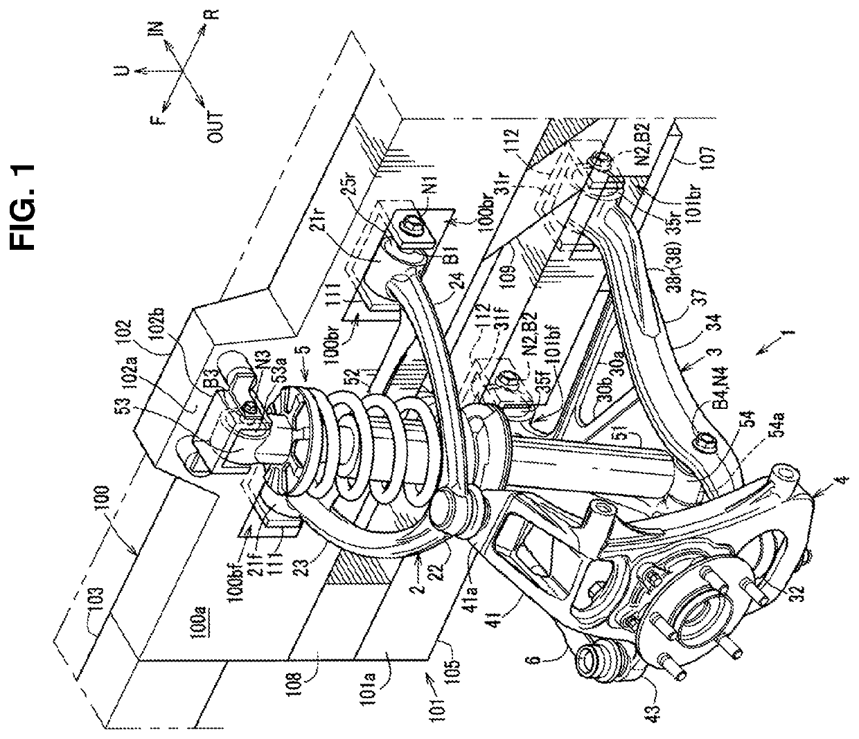
[0027]Hereafter, an embodiment of the present invention will be described specifically referring to the drawings. In the following discerptions, an arrow F shows a vehicle forward side, an arrow R shows a vehicle rearward side, an arrow IN shows an inward side in a vehicle width direction, an arrow OUT shows an outward side in the vehicle width direction, and an arrow U shows a vehicle upward side in the figures.

[0028]Herein, right-and-left front suspension devices 1 are symmetrical laterally, so the left-side front suspension device 1 will be described.

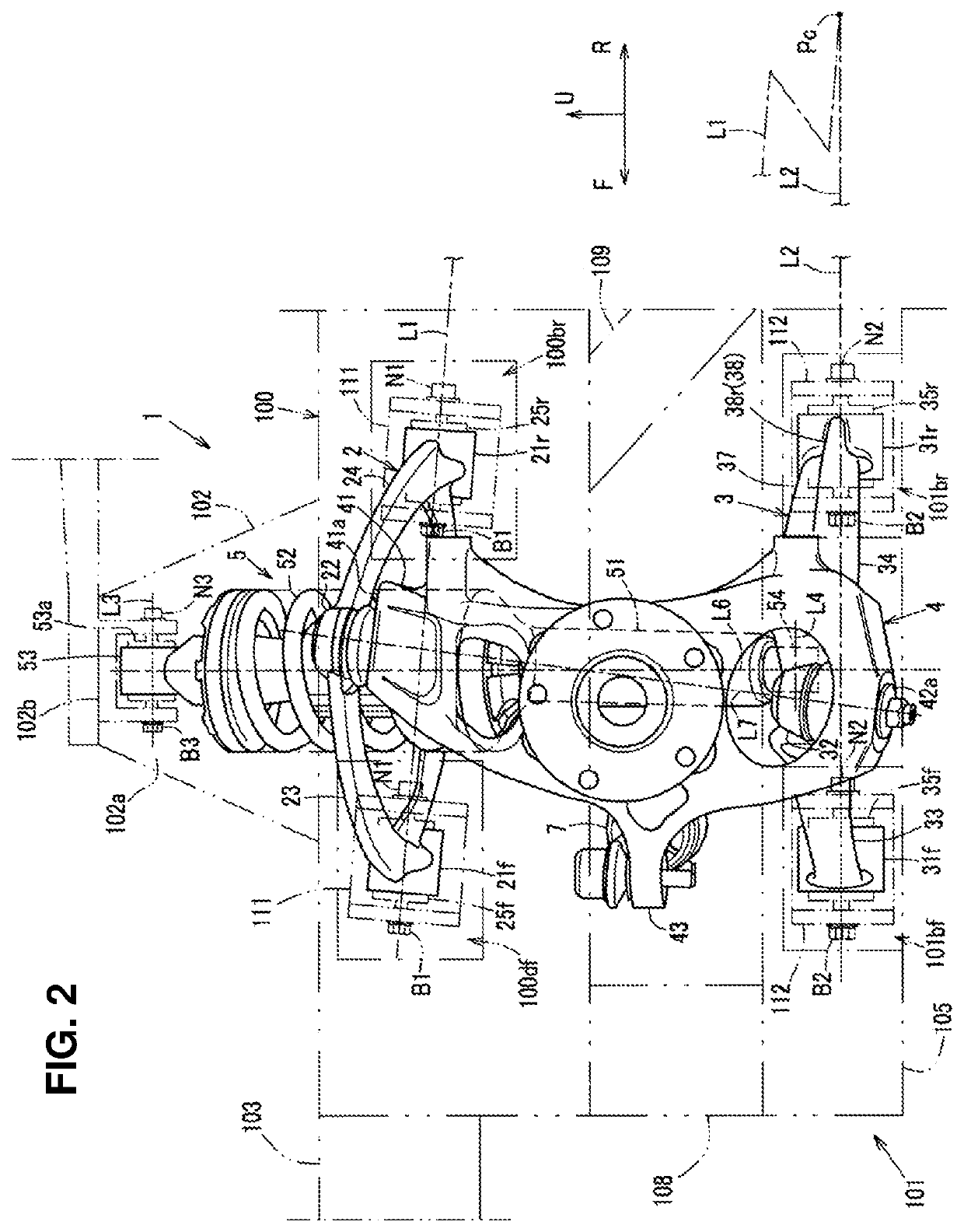
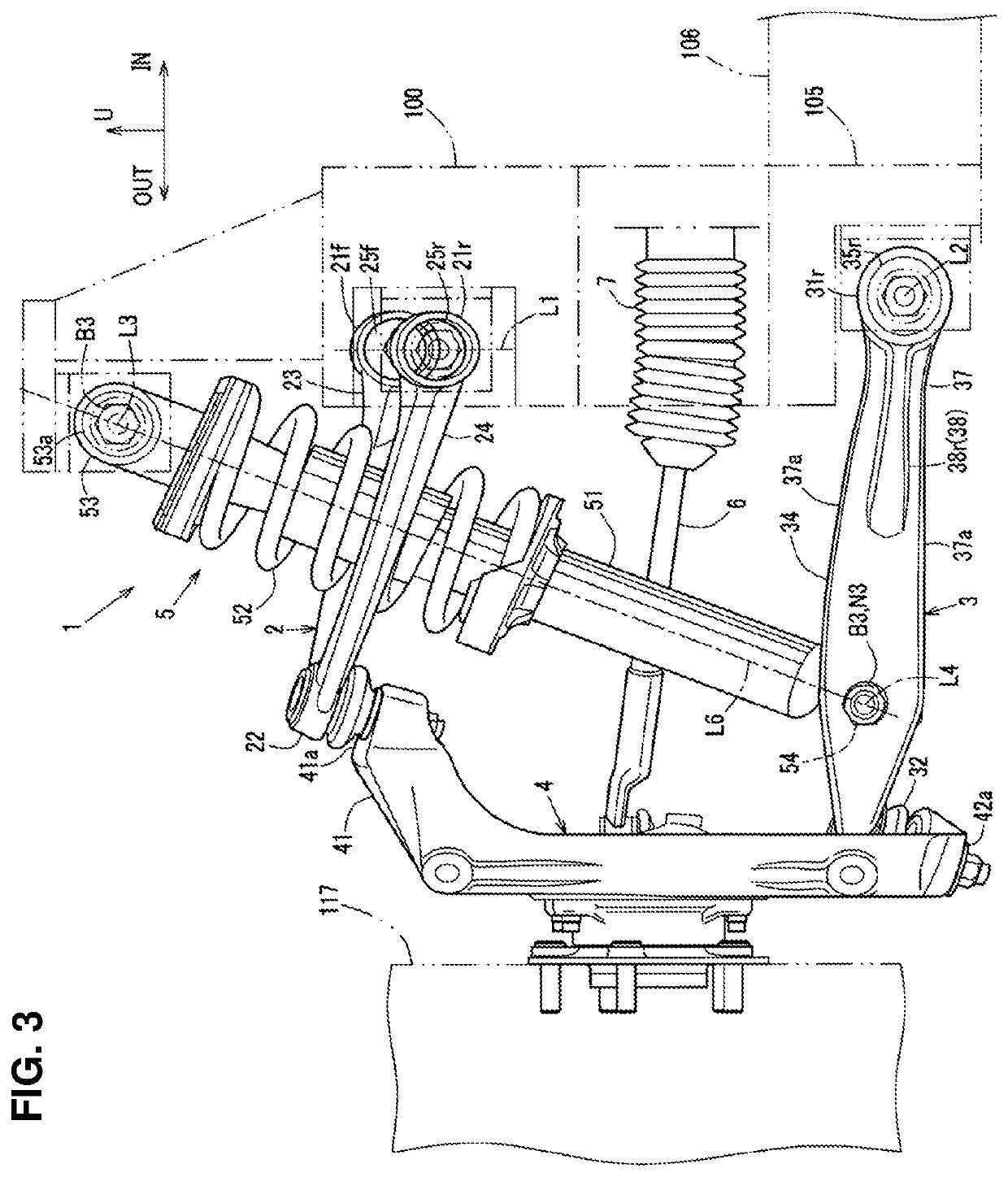
[0029]The front suspension device 1 of the present embodiment is, as shown in FIG. 1, arranged between a front side frame 100 and a front sub frame 101 which are provided at a vehicle-body front portion, and this front suspension device 1 is a double-wishbone type one which comprises an upper arm 2 which is attached to the front side frame 100, a lower arm 3 which is attached to a front sub frame 101, a wheel support member 4 (a whee...


PUM


Abstract

In a double-wishbone type front suspension structure, upper and lower arms are pivotally supported at a vehicle-body side via front-and-rear pivotal portions, axial lines of resilient bushes of the front and rear pivotal portions of the arms extend in a longitudinal direction, a knuckle-side pivotal portion of the upper arm is positioned in back of a knuckle-side pivotal portion of the lower arm, and a lower end portion of a damper unit provided between a vehicle body and the lower arm is connected to the lower arm such that the damper unit is positioned perpendicularly to the axial lines of the lower arm in a side view and an upper end portion is pivotally supported at the vehicle body via a rotational axis extending in the longitudinal direction.

Description

BACKGROUND OF THE INVENTION[0001]The present invention relates to a front suspension structure of an automotive vehicle, and in particular, relates to a double-wishbone type front suspension structure of an automotive vehicle.[0002]As the double-wishbone type front suspension structure of the automotive vehicle, there exists a structure in which respective vehicle-body-side end portions of two arms (an upper arm and a lower arm) which are arranged vertically and extend in a vehicle width direction are pivotally supported at a vehicle-body-side member, respective wheel-side end portions of the two arms are connected to a knuckle member (a wheel support) which rotatably supports a wheel via respective ball joints, and a damper unit is provided between a vehicle body and the lower arm. This structure has been used widely.[0003]Herein, another type of structure as the double-wishbone type front suspension structure, in which the damper unit is arranged such that it is inclined toward a ...

Claims


Application Information

Patent Timeline
Patent Type & Authority Patents(United States)
IPC IPC(8): B60G3/26B60G3/20
CPCB60G3/20B60G3/26B60G2200/144B60G7/001B60G2204/129
Inventor ANDOU, FUMITAKAASANO, NORIOTAKAHASHI, KOJI
Owner MAZDA MOTOR CORP
Why Eureka
Try Eureka